GJD020 Passive Infra-red Motion Sensor Review
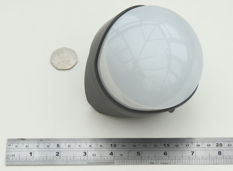
The GJD GJD020 'Opal XL' PIR sensor is a high-quality, external motion sensor. It can be configured to work as a long-range (35m) sensor, support pet immunity, or as a short-range 'curtain sensor'.
We purchased this one for review for about £45 including delivery from Alert Electrical. This is not cheap but, you need good quality, outdoor PIR sensors, if they are to work well in smart home applications.
The objective of this review is to test the sensor with a wide range of smart home use cases, to see how well it performs. When connected to my contextual smart home it will provide useful occupancy information and other context such as zone activity levels, to allow my smart home to intelligently control lighting, water features, a robotic lawn mower, irrigation, etc. It will also be used for security applications, including the triggering IP cameras and infra-red security lights.
Specification
This 'Opal XL' PIR has an ABS housing (approximately 10cm in diameter) with a white polythene UV stabilised lens cover, providing an IP55 rating. The internal electronics module can be adjusted both horizontally and vertically and it features a digital ASIC / microprocessor.
- Operating voltage: 9 to 15V dc
- Operating current: 6mA typical
- Detection range: 10m to 35m (configurable)
The sensor has two outputs, both rated at 25mA max:
- 'A' is an open collector (-ve switching) output that triggers for 400mS every time the sensor is activated and is not affected by light levels.
- 'S' is an open collector (-ve switching) output with a 60s activation (re-triggerable) and can be limited by an adjustable light-level sensor. This would typically be used to directly drive security lighting.
The 'A' output is the one I'm interested in. It can be used with an Arduino, Raspberry Pi, etc. to detect motion in a timely manner. The ability to send pulses in quick succession means it can be used by my contextual smart home to monitor the activity level and work better for occupancy detection.
Connections
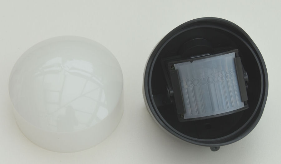
The installation and configuration process is clearly explained in the the GJD020 manual.
To gain access to the sensor module, the lens cover needs to be removed. This has a subtle logo and a tiny drainage hole, which need to be at the bottom.
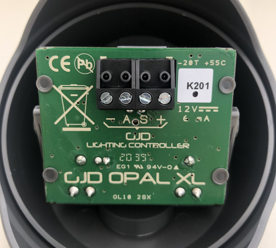
Rotating the PIR module, reveals the screw terminal connections at the rear. The manual describes how to connect them.
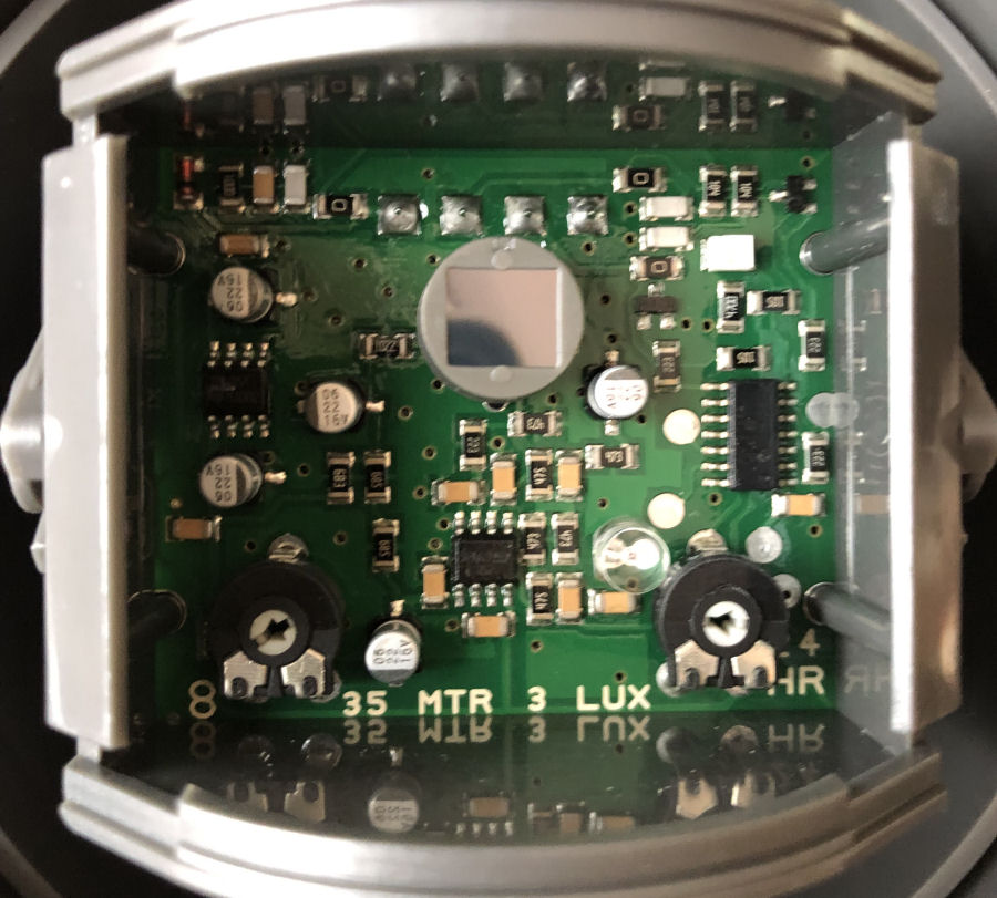
Popping out the Fresnel lens from the front, allows access to the module's potentiometers, to adjust the range and light level sensitivity.
Testing

The manual shows how to connect a 12V sounder/buzzer for testing coverage. I planned to test this PIR sensor in a number of locations and configurations, so I fitted a 5m length of 4-core alarm cable to it:
+ = red, - = black, A = blue, S = yellow
For testing, I used a 12V battery and a 12V buzzer with a 150Ω resistor is series, to limit the current to 18mA. This means I could easily test it in lots of different locations and hear when the PIR is triggering. There is a red LED that flashes for a few seconds on applying power but, it is not on when the PIR is in normal use.

Out of the box, the sensor supports long-range, multibeam coverage. I fitted it above my garage door, to test the range over my drive.

The sensor can be configured to provide curtain coverage by masking some of the lens with tape (supplied).
Orientation
The sensor has to mounted the right way up and pointing in the right direction horizontally. It can be adjusted vertically internally. Although it claims to be adjustable horizontally, this isn't really the case. The 'forked' mount for the sensor module can only rotate at its base and this limits the range of movement.
Mounting
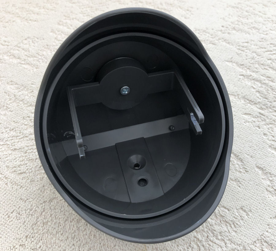
The shape of the housing makes mounting a little challenging in some cases because internal module mount is fixed to the top face. It is easy to mount it on the underside of a flat surface and also fairly easy to mount on a vertical surface. It would also fit quite well in a 90° vertical corner. Everything else needs a bit more thought. The cable exits on the 'bottom' face so unless it runs through the mounting surface as well, it will be in the way.
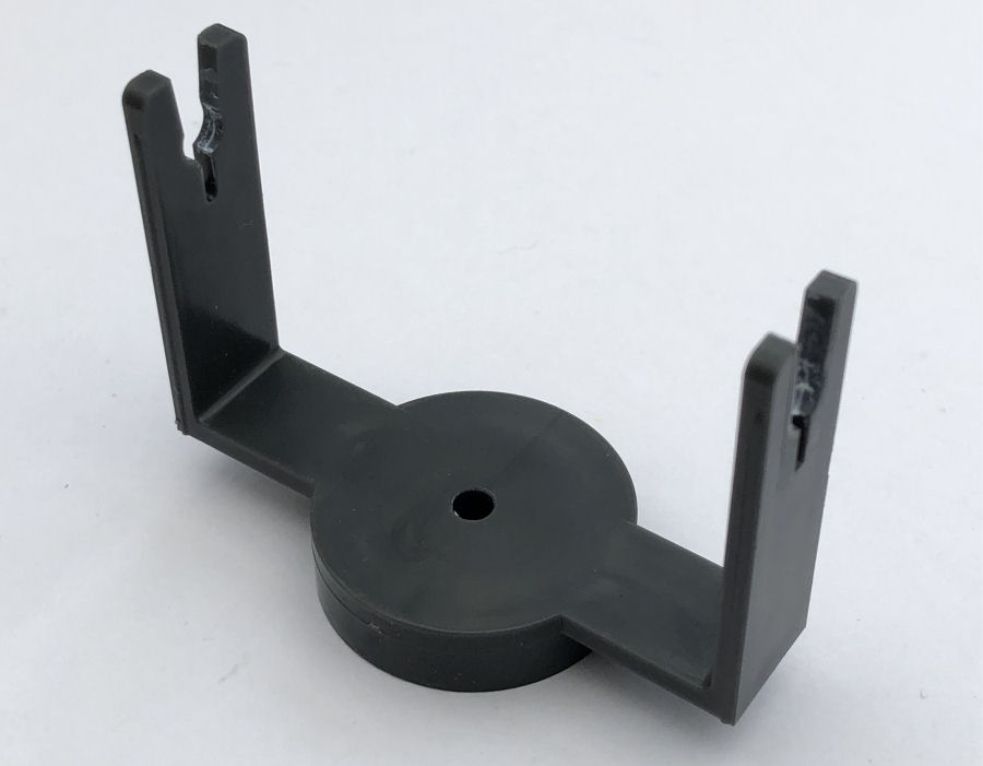
The internal mount is easily removed and is held in place by one screw.
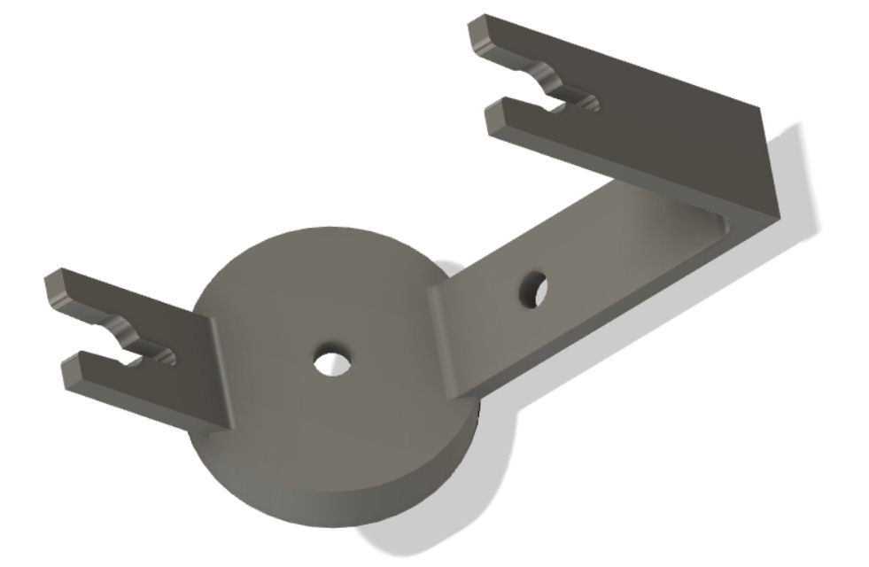
This housing shape lends itself perfectly to a 3D printed module mount that enables the housing to be mounted at 90° into a vertical corner, so I designed a new sensor module mount using Autodesk Fusion 360. I measured the existing bracket and then added the alternative mounting point. This now gives me more mounting options but, this new mount doesn't have quite the same clearance for the sensor module and thus has more limited vertical adjustment.
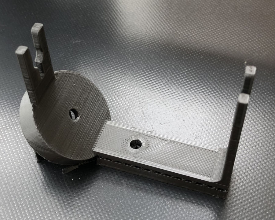
This is my new 3D printed mount, printed on my Ender 3 Pro 3D printer. It worked really well during my testing. You can download the STL file.
Field Of View
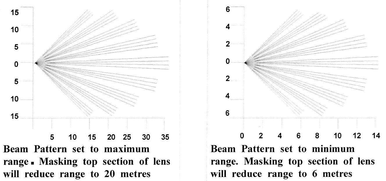
The field of view horizontally is about 90°. Vertically, it depends on the configuration and installation.
Range & Sensitivity
The range and sensitivity are adjustable by using potentiometer in the module and by using the supplied tape to 'configure' the sensor, essentially masking off areas of the sensor. The sensitivity and range can also be adjusted by tilting the sensor accordingly. In this respect, there is quite a lot of set up required to optimise it for each installation. This is good though, as it will improve performance and minimise false triggering.
I started my testing with the range adjusted to its minimum setting but this didn't even cover my patio, so I ended up turning it up more.
One problem with some occupancy sensors is false triggering. A lot of this can be fixed with good positioning but, some sensors are simply susceptible to it. My testing shows this sensor to be very good in this respect. I have yet to experience any false triggers.
Use Case Testing
I have a number of use cases that I will be testing against:
Drive
With a PIR sensor mounted in the back corner of my drive, it will be used to detect Drive occupancy and turn on security lighting, trigger a IP camera, etc. My drive is about 5m wide and 9m long. I need to be careful that people walking along the pavement at the end of my drive don't trigger the sensor, so adjustability is important.
My testing showed that it worked really well when using my new mount. I provided good drive coverage, without being triggered by people walking along the pavement at the end of my drive.
Porch
With a PIR sensor mounted over my front door, it will be used to detect Porch occupancy and turn on 'welcome lights', trigger a IP camera, trigger a voice announcement, etc.
I tested with my new mount as it fits better against the door frame, when mounted at 90°. With the sensitivity turned right down, it was very accurate in picking up people coming up to my front door.
Patio
My patio is about 4m by 4m square. As far as my contextual smart home goes, it is a zone in it's own right and turn on certain lights when the patio is occupied.
I mounted the PIR to one side of the patio, quite high up on a wall. The results were again really good.
Garden
I have a number of sensors used to detect garden occupancy. One thing this is used for is intelligent control of a robotic lawn mower.
I tested this sensor mounted on in two locations on the outside of my conservatory and it worked really well. One thing to note though, is that washing blowing on a washing line seems to trigger the sensor.
Garden
I'm in the process of building a new 'garden lounge' and have no doubt this sensor will work well in this use case too.
Smart Home Integration
Over my many years doing smart home (I started in 2004), I have developed my own library of code for Arduino processors and this includes functions to integrate it into my distributed Home Control System and connect numerous types of sensors. These 'slave processors' can then do clever stuff like local control, self-monitoring of performance, local signal conditioning and rate limiting, send warnings and errors, or host some functions locally.
This maximises reuse across my many smart home projects, making it very quick and easy to develop and test new smart home capabilities. My smart home also employs the concepts of technology abstraction, meaning my smart home is also technology agnostic. This allows old technologies or broken sensors and devices to be swapped out with new ones, with minimal effort and zero reconfiguration.
Most of the Arduino processors installed in my smart home use an Ethernet IP network interface, to enable them to send and receive events with my Home Control System, using my unified communications protocol. Wired networks ensure very low latency and hence a great user experience, though occasionally I will use Wi-Fi.
Adding sensors and devices to my Home Control System is simply a matter of adding one line of JSON for each one, to the main configuration file. This defines the name, zone, object type and also the details of the slave processor it is hosted or controlled by. All the intelligence is within my Home Control System, which receives and sends encrypted events using my unified communications protocol. It sends events to update my smart home on things like the temperature, humidity, fan state, appliance and lighting state changes, occupancy, etc.
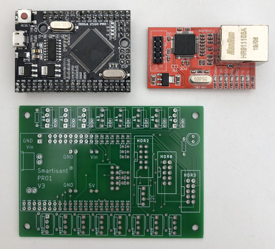
Typically, I use my Smartisant Arduino PRO1 PCB board (V3) to connect 'dumb' sensors to my contextual smart home. I've been using Arduino devices like this in my smart home for 10+ years, many in very harsh environments. They have been 100% reliable and provide excellent performance at very low cost.
In my contextual smart home, these PIR sensors have a object type of 'Motion'. Motion sensors generate events when motion is detected and send a value of 'On'. Depending on the type of motion sensor, the slave processor they are connected via will perform rate limiting, so that they don't generate events too frequently. This could be as low as every 1 second but is more usually around 7 seconds, depending on the type of zone they reside in and what other context I need them to support.
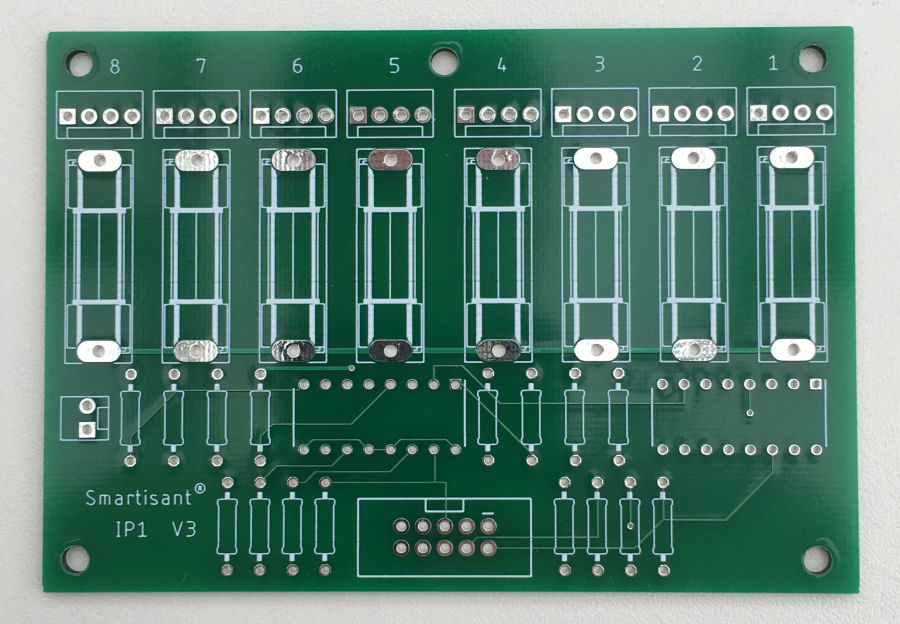
I also normally use my Smartisant 8-channel 12V fused input board IP1 to connect 12V sensors as it gives better protection.
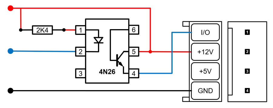
My input board expects a switched (positive) 12V input but, this sensor has an open-collector output which pulls my board input to ground. To convert it, I've added a 4N26 opto-coupler and a single resistor, which sits inside the sensor housing.
When the sensor output is pulled to ground, this 'lights' the internal LED in the opto-coupler and switches on the internal transistor, connecting the 12V supply to the input on my 8-channel input board. The 2.4KΩ resistor limits the current through the LED to about 5mA.
Example Installations
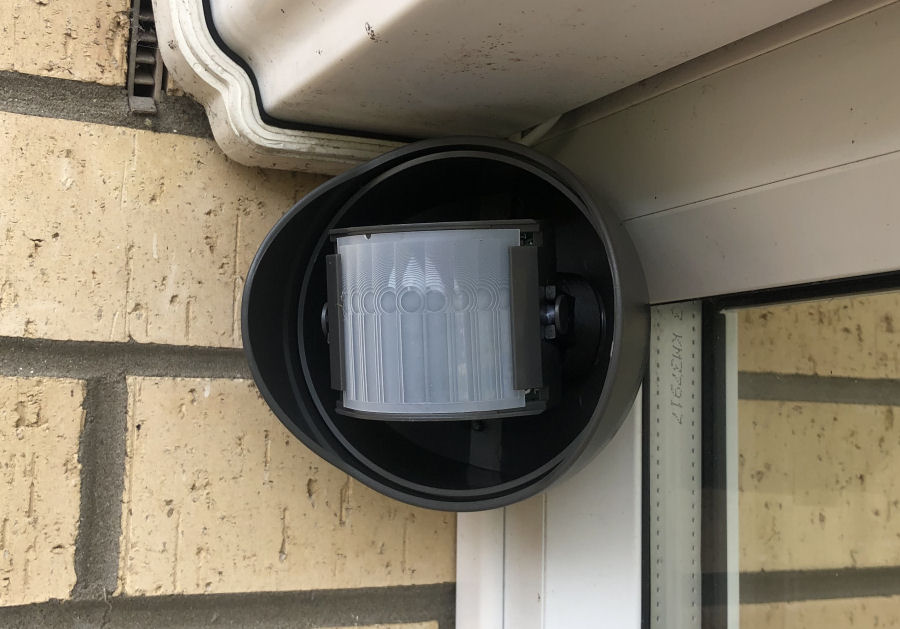
This is the 'Garden Right PIR' installed (shown without cover) in my garden. It's mounted at 90° because it was much easier to fit it flush to the wall and the side of my conservatory this way. It's in a sheltered position under the guttering but covers most of one side of my garden. I've used my 3D printed sensor module bracket to allow the module to be in the correct orientation.
For this install, I have set the sensitivity to about 70% and have not masked off any parts of the sensor window. The event rate is limited to once every 7 seconds for this PIR sensor.

Occasionally, my @smartest_home will tweet about this sensor.
Summary
My testing has shown that the performance of this PIR sensor is really good. The provision of a 'fast response' output that is not light level dependent is one of the key reasons I chose it. The range and sensitivity adjustments, mean that performance can be optimised for each installation, resulting in no false triggering.
Whilst the GJD020 PIR sensor is fairly large, it is quite nice on the eye and provides excellent performance. Based on my testing so far, I plan to deploy it in many more locations. It isn't cheap but the performance, justifies the investment in my view. It is possible to by the white lens cover separately, which is also a nice touch.
I currently have several of these sensors installed in my garden and being testing in real use cases.
Further Reading
- My research on smart home sensors.
- My research on PIR sensors.
- Smart home zone activity tracking.


