Ender 3 Pro 3D Printer Review

The Creality 3D Ender-3 Pro V-slot Prusa I3 DIY 3D Printer (to give its full name) is an entry level 3D printer. I purchased this model based on reviews and the experiences of friends who have also bought this printer.
The printer supports a 220 × 220 × 250mm printing size and the Pro model comes with a magnetic removable print bed, which I immediately upgraded to a glass print bed.
I bought my printer and glass print bed from ReprapWorld.
Upgrades
There are a few upgrades I'm fitting as I assemble my 3D printer:
Heated Glass Bed
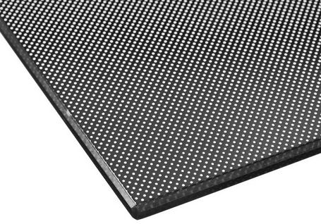
I've upgraded to the Creality heated glass bed because this will improve print quality a lot, by providing a flatter and more consistent surface to print on. It is 235 × 235 × 3mm. I doesn't come with retaining clips but I'm just using a couple of bulldog clips.
Drive Feed / Extruder
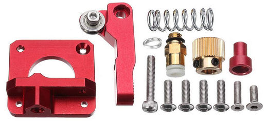
I've upgraded the extruder and fitted this Vibury MK8 aluminium drive feed and extruder, simply because the plastic parts fitted can wear and a consistent feed is crucial to good quality prints.
There is a nice YouTube video showing you how to put it together.
Bed Springs
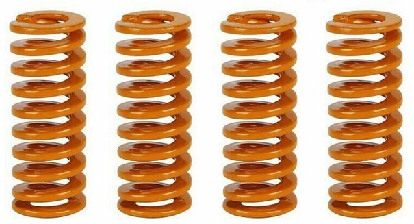
I'm fitting these upgraded bed springs. These cost £5 and were purchased on eBay.
Feeder Fittings & Tubes
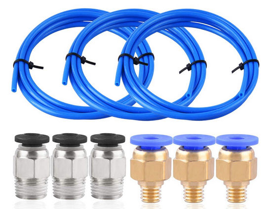
I've upgraded the feeder fittings and tubes to Teflon tube made of PTFE (Poly Tetra Fluoro Ethylene). These cost £8.49 on Amazon.
In The Box
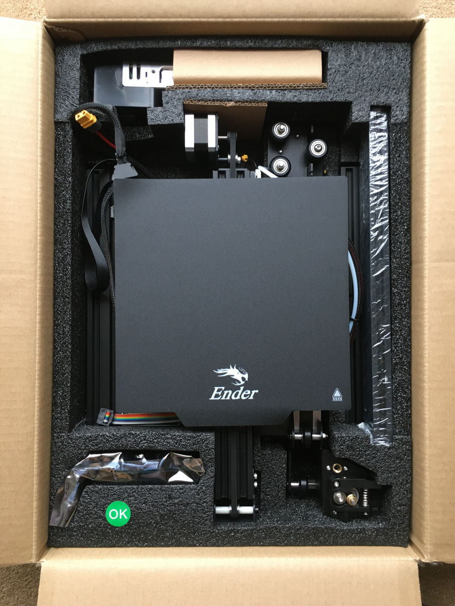
The printer comes well protected inside its box and is partially assembled. There is still a fair bit of assembly to do though. Everything is packaged in small plastic bags that are clearly labelled.
Inside the box is also a USB drive (micro SD card + USB adapter) with all the documentation required. This included the assembly instructions, V2.2 in my case.
Assembly & Setup
The printer needs some careful construction and calibration before it can be used and you need to allocate 2 to 3 hours to do this properly. You can download the Creality 'official assembly instructions' from here but they are also on the supplied USB drive. I mostly followed a YouTube video as it is so much easier to see what's going on but, I did refer to the instructions a few times to check things.
I thoroughly recommend you watch this YouTube video before you start to put an Ender Pro 3D printer together. I followed it to assemble my printer.
The first thing I did was replace the Bowden tube couplers with my upgraded ones. You push the outer collar down to remove the tubing. The printer comes with all the required tools to assemble it. The new couplings feel more solid and have a much more positive action.
Build Plate
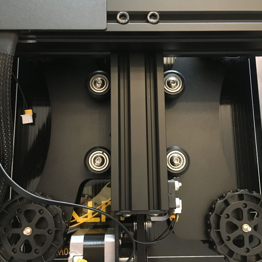
The next part involved working on the 4 wheels underneath, so work I worked on on my printer upside down. You should not rest it on the print bed (as you can bend this), so I used two boxes to support it by the side rails. Firstly, I tightened the hex head button bolts through centre of each wheel as these were shipped slightly loose. This is done with the supplied Allen key.
Two of these (on the right as you look from underneath) are on hex shaft and spin to adjust wheel pressure on aluminium rail. Pushing spanner away from me loosened the wheels.
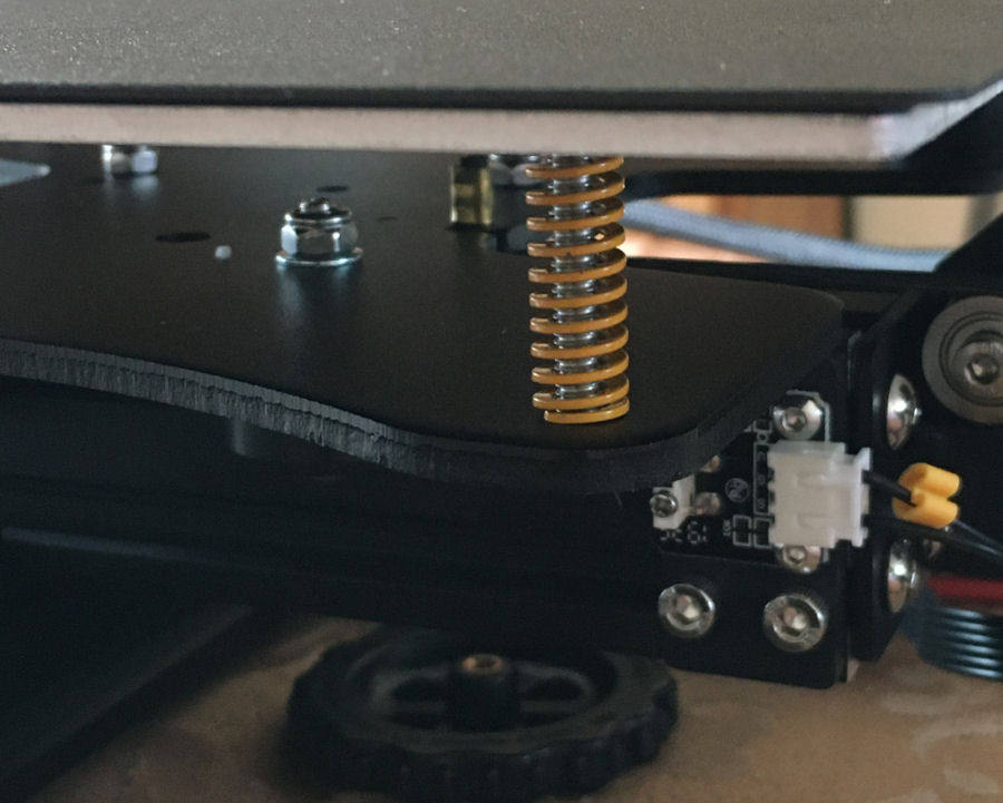
At this point I then replaced the print bed springs with my new upgraded ones. I then tightened the wheels clockwise to fully compress springs, then rotated them a couple of turns counter clockwise.
Verticals
The video linked above mentions moving the cover plate if it fouls the point that the aluminium extrusion uprights fit but, my printer has a modified cover plate for the electronics which ensures this can't happen.
As described in the video, the challenge is to make sure they are completely square and the spacing at the top and bottom is equal. This was easier with a pair of clamps and using one of the other rails as described in the video. I checked the width at top and bottom, using a 1m steel rule.
Wheel Carriers
The trick with the carriers is also to tighten eccentric nuts so there is no wobble, but must drop on its own using gravity.
LCD Screen
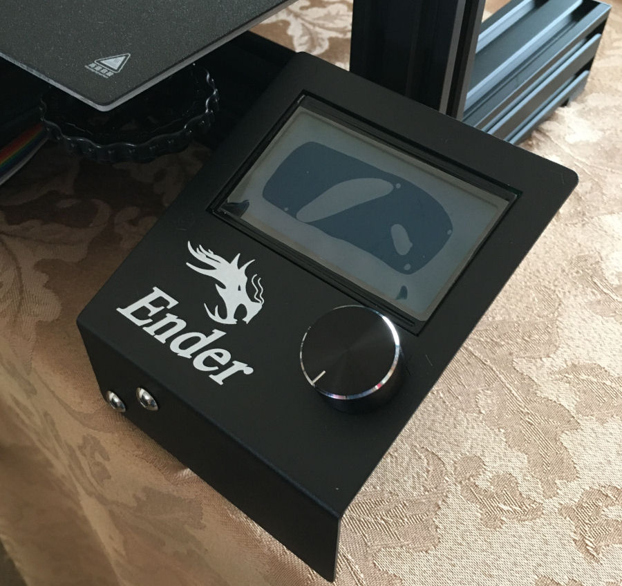
I fitted the LCD screen with two M5 x 8mm long bolts. The wiring is done later.
The rotary knob is used to select menu items and then pushed to action them.
Power Supply
I made sure the PSU was set to 230V and fitted it with two M4 x 20mm screws.
Z-Stop Switch
I fitted this, making sure the locking tabs had the correct orientation to fit into groove.
It is important that this is fitted high enough, so that the extruder nozzle does not hit the bed. It is made of brass and is quite soft and easily damaged.
Z-Axis Motor
Before this is fitted, I tightened the grub screw on motor shaft and loosened top grub screw to insert drive shaft. This is then done up tight to clamp the drive shaft. I fitted the motor bolts using the two M4 x 18mm bolts.
X-Axis Motor
I then fitted the extrusion to the motor carrier. The countersunk holes face to the rear, to sit over the heads of the bolts already in place. This is done with two M4 x 16mm bolts. It's quite fiddly as the bolts are mounted from inside the two plates. Fortunately, there are holes in the second one to allow them to be tightened up.
Upgraded Extruder
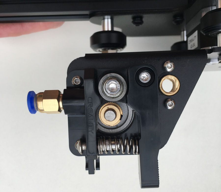
At this point I replaced the old plastic extruder with my upgraded aluminium one.
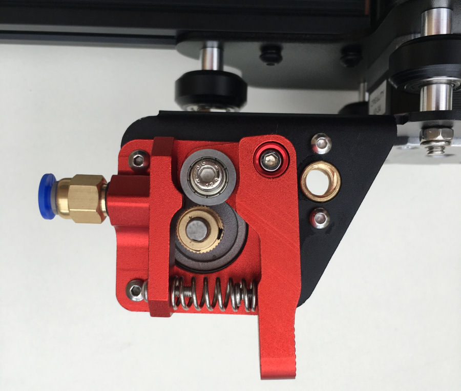
The new extruder fitted. This is made of aluminium.
X-Axis Motor
The horizontal extrusion for the X-axis was mounted previously but there is enough play in the bolts to allow this to be fitted in a position that is a long way from horizontal and it needs to be exactly horizontal. At this point I checked the height of both sides against the top of the base extrusions using a steel rule, to make sure it was horizontal. It was quite a way out initially and I had to adjust it before I was completely happy with it.
X Drive Belt
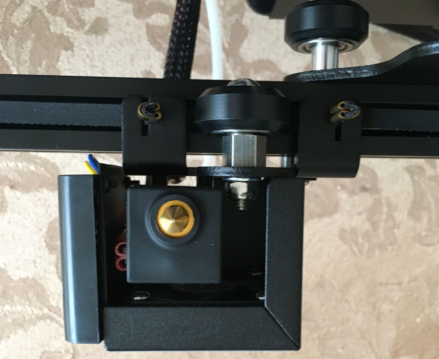
It is best to watch the video for this bit as it involves lots of steps. I put the first assembly on and then fed through the belt. It's important that the belt sits centrally in the slots and hence runs smoothly down the centre of the channel in the extrusion. I then fitted the second carriage.
I fitted the belt tensioner, using my thumb to put pressure on it, whilst I tightened the bolts. I made sure it could hit the X-axis stop switch.
Using the drive shaft coupler, I then fitted the completed assemble onto the vertical rails. I ran it from top to bottom before tightening the drive shaft bearing, to ensure it was smooth along the full length of travel.
Top Extrusion
I fitted this using four M5 x 25mm bolts. My printer also came with some plastic caps to go on the ends of this extrusion.
Filament Holder
Unlike in the video, my filament holder just had a locking nut with lugs and not threads. This is fitted using two M5 x 8mm bolts and two T-nuts. This is mounted to the far left hand side.
Wiring
Connecting the wiring was all pretty easy as the connectors are polarised and have yellow tags indicating their position.
The supplied cable ties fitted to the cables were too tight, so I cut them off and fitted some more with a bit more give. I actually think some double sided Velcro would work much better and will look at this later.
Power Up
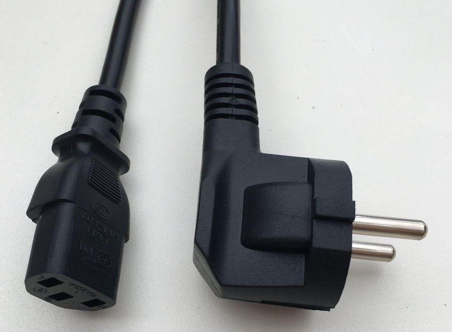
Finally I get to power it up. This is where I discovered that my printer came with a European power lead :-( Fortunately I have plenty of UK equivalents :-)
To check it is working, to rotate the wheel on the display and push it to select the required action from the menu. The first test is to select 'Prepare' > 'Auto Home'. This worked as expected.
Bed Levelling
Bed levelling is crucial to getting good prints, so you need to take the time to do it right and use the tools to check it is right too. A glass print bed gives a more consistent and flatter surface, which was why I upgraded mine.
I found this video on manual bed levelling to be really useful. There is an associated web page where you can download some gcode files to help set up and test.
- CHEP_ender_3_bed_level.gcode
- This file just moves the head to the four corners and centre in turn, allowing you to test the bed height with a piece of paper. You press the printer dial to progress to each point. You don't need to set the bed and nozzle temperatures as it doesn't extrude PLA.
- CHEP_bed_level_test.gcode
- This prints a series of squares on the bed to test that it is level. I set the nozzle temperature to 200°C and the bed to 60°C. This test print takes over 13 minutes to complete.
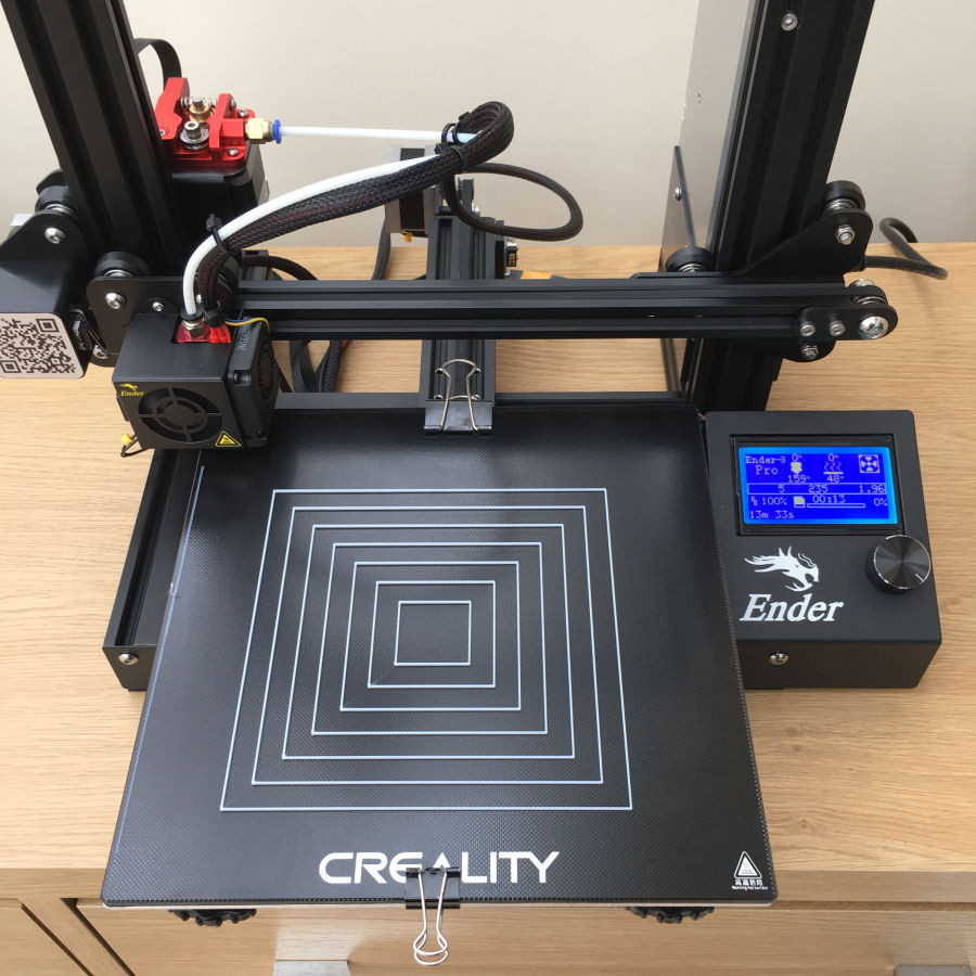
When I run the bed levelling gcode, I use a PostIt note under the nozzle, such that I can just feel the drag between the bed and the nozzle. This seems to work really well.
The bed level test prints a series of concentric squares and goes over them several times to build 'walls' that are about 2mm high.
Extruder Calibration
This calibration ensures that the extruder is pushing exactly the right amount of filament through the hot end during a print:
- With a steel rule up against the entry face of the extruder, mark the filament at 100mm and 120mm.
- Heat up your hot end and extrude 100mm by selecting 'Prepare' > 'Move axis' > 'Extruder' > 'Extruder 1mm' and then rotating the knob until you get to 100mm.
- Wait until the printer has finished extruding and measure how far off the 100mm mark the filament stopped. In my case it was 4.5mm short of the 100mm mark.
- I then looked at the current value for E-steps under 'Control' > 'Motion' > 'Step/mm'. In my case this was set to 93.00.
- I then calculated the correct E-steps by multiplying 100 with the current E-steps setting (93.00), then dividing this by 95.5. This gives a new correct E-step value of 97.38.
- I then stored this new value using 'Control' > 'Store settings', which results in a beep from the printer.
- I then re-ran the test to check this new value was correct.
Heat Tower
This heat tower helps you find the best temperature for your filament. It allows you to print steps from 190°C to 240°C.
Calibration Cube
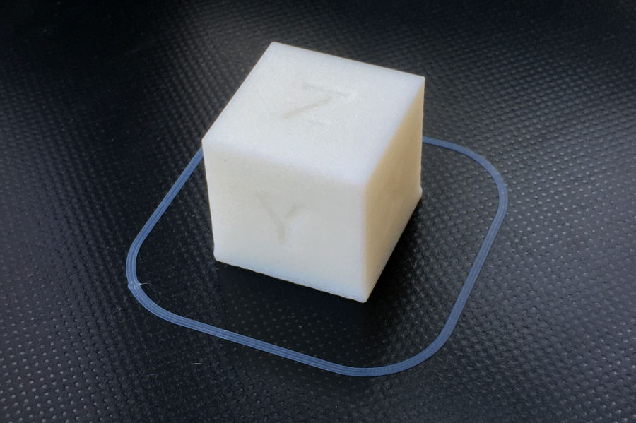
This 20mm × 20mm × 20mm calibration cube is a good way to verify all the axis settings are dimensionally correct. You can download the STL file from here.
I used a nozzle temperature of 205°C and a bed temperature of 55²C, to minimise distortion on the first layer. Once printed, I measured the dimensions of the print with my digital vernier gauge. My cube was 20.0mm in the X-axis, 20.0mm in the Y-axis and 19.5mm in the Z-Axis. This is due to the visible "elephant foot", where the first few layers get squashed or sag by the heat of the bed.
In Use
Designs
Pretty much all of my designs are created using Autodesk Fusion 360. It's an extremely powerful tool and I like it a lot. Every time I use it, I learn something new :-)
Slicing
I'm using Cura (V4.5) to translate my STL files to a gcode file. Cura shows you the print bed and the object to be printed. Sometimes you need to rotate objects to get them to print the way you expect them to sit on the print bed. Cura uses profiles for each make and model of 3D printer and it knows about the Ender 3. It knows it has a 0.4mm nozzle and uses a 'Standard Quality' of 0.2mm (essentially the height of each layer).
One thing I love about Cura, is that when you do the slicing it gives an estimate of the amount of material being used for the object being printed (in grams), the length of filament being used (in meters, so you ensure you won't run out mid print) and also the time it will take to print the object. Larger objects can take several hours to print!
Cura also lets you preview the layers as they will be printed.
Printing
Before you do your prints, you need to set the nozzle temperature and bed temperature. I started with 200°C for the nozzle and 60°C for the bed.
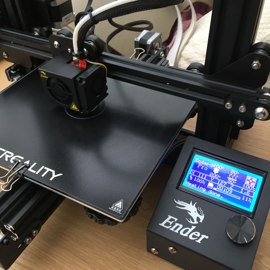
Time to try my first print! This was actually a quite complex 16-tooth HDT5 cog I designed for one of my smart home projects. The result was really good :-)
Tips
- Have a bin close by! For odd bits of PLA, used kitchen roll, etc.
Consumables
PLA Filament
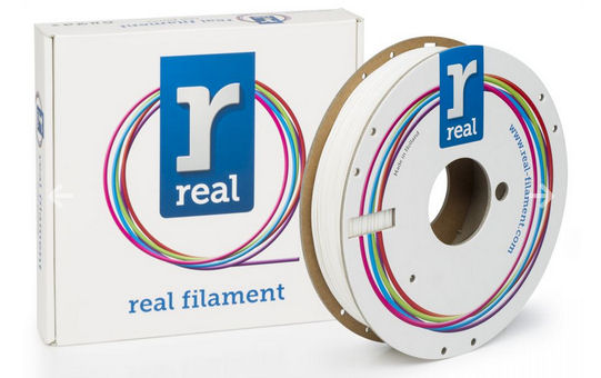
This 3D printer uses a 1.75mm diameter PLA (polylactic acid) filament and I'm buying it in 500g reels. It comes in many colours but I'm mostly using white for now. PLA less resistant to the outdoor elements (UV light and water) than other common thermoplastics.
ABS Filament
The Ender 3 Pro can also print in ABS (acrylonitrile butadiene styrene). Heating this causes noxious fumes, so it needs to be in an enclosed environment or a very well ventilated space. I do most of my 3D printing in a conservatory at the moment, so I can open all the windows and roof vents. I've yet to try printing in ABS so far but I will be giving it a try soon. When printing in ABS, you need to keep the ambient temperature fairly high though, to stop the ABS warping.
Isopropyl Alcohol (IPA)

IPA is used to clean the print bed before each print. I bought mine on Amazon as a 1 litre bottle.
I wipe the surface with a bit of kitchen roll and some IPA. I notice that after each print the kitchen roll is stained slightly yellow, so it is definitely cleaning something off the bed.
Improvements & Accessories
There quite a few people using this printer and over time a number of 3D printable upgrades and accessories have been designed:
Summary
I have bought this particular printer because I prototype a lot of things for my smart home work. A friend also has this model (and upgrades) and has printed a few parts for, so I know the print quality is good and perfect for my needs.
Examples
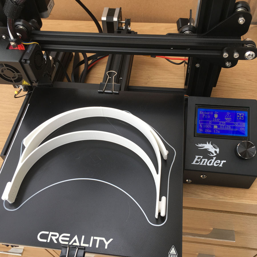
I've been printing Personal Protective Equipment (PPE) for our local hospital to help in fighting the Corona Virus. The first print took over 11 hours but, I've got it down to about 3 hours and 26 minutes now.
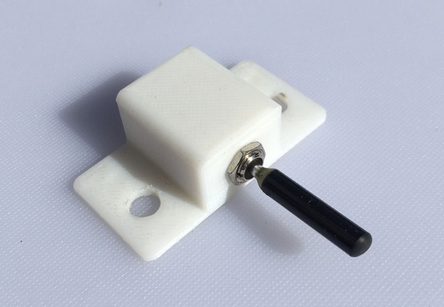
This is ultra light-weight indicator switch and 3D printed mount for my 450kg kitcar. Including the switch it weighs just 10.0g and is bolted through to the paddle-shift using the existing bolts.
This was also a test to see how well the Ender 3 bridges over gaps. It did an amazing job and I wished I'd watched do it because I still can't quite beleive it!
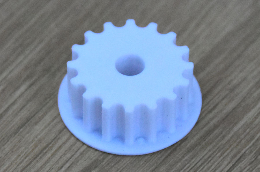
This is an HDT5 profile belt return pulley that I designed and printed for my smart home automated curtains project.
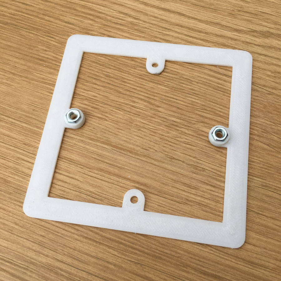
A project to enable easy rotation of light switches by 90°.


