Shed Path Project

This is a project, I've been meaning to do for a while but, having dug up most of my garden as part of my 'Smart Pond' project and 'Smart Garden Lounge' project, it made sense to put in the ducting and infrastructure to finally do it properly too.
As with most of my contextual smart home, I'm aiming for invisible sensors and devices where possible and a zero touch user experience.
Implementation
Shed Path Light

When I looked at the underside of the window sill, I could see a channel along the whole length, 36mm wide and 15mm deep. This was just perfect to fit some 16mm × 16mm trunking (on the inside) and some 90° aluminium profile up against it, to allow an LED strip to be mounted at 45°, pushing the light both out and down.
I used an external frame sealant to fix both the trunking and the aluminium profile. The ducting carries wires for the power and also a 4-core alarm cable for the beam break sensor.

The aluminium profile comes in 1m lengths, so I've joined three together. It also comes with end caps.

Although the LED strip can't be seen, I'm using a semi-clear diffuser to soften the light and to protect the LED strip from the elements. I'm using a warm'ish white 5m long LED strip (cut down to 3m) and it is 8mm wide. It requires a 12V dc power supply and the power required is about 1.5A for the whole 5m (16W) but, I'm using less than 3m (so about 0.9A / 10.8W).
Beam Break Sensor

The shed path light is triggered by many things but I'm primarily using a beam break sensor because these provide the most accurate and timely detection, with very low latency. They are also the best sensors in terms of lack of false triggering. These are mounted at the end of the path, so simply walking towards the shed will light up the path.
Some people use PIR sensors (motion sensors) but, these will give a much poorer user experience in this type of application, will be falsely triggered by wind, etc. and have a much wider field of view.
Before I installed the beam break sensors, I opened them up and used insulation tape to cover up the bits I didn't want covered in PCB lacquer. The PCB lacquer is over-kill really but it basically protects the sensor better from moisture and should make them very reliable.

This is the beam break sensor receiver and it is mounted it at about hip height to give best detection performance but also to allow it to be protected from the elements by the window sill. Some 4-core alarm cable runs to this unit. It has a small internal relay (which can just about be heard in operation), to switch a 12V signal.

This is the beam break sensor transmitter mounted on a wooden post, opposite the receiver. This allows me to hide the wires inside the post. It requires just a 12V dc power source.
Both modules have an O-ring to prevent water ingress via the cover. You will notice, that I've also used black silicon sealant over the front screws on these modules, to protect them from the elements too.
Shed Door Light

I was really pleased with the way the shed path light turned out, so I used some of the spare LED strip in a 50cm length of 10mm flat profile above the shed door as well. It's just the right width to sit nicely under the 'eave' of the shed roof.
Smart Home Integration
Over my many years doing smart home (I started in 2004), I have developed my own library of code for Arduino processors and this includes functions to integrate it into my distributed Home Control System and connect numerous types of sensors. These 'slave processors' can then do clever stuff like local control, self-monitoring of performance, local signal conditioning and rate limiting, send warnings and errors, or host some functions locally.
This maximises reuse across my many smart home projects, making it very quick and easy to develop and test new smart home capabilities. My smart home also employs the concepts of technology abstraction, meaning my smart home is also technology agnostic. This allows old technologies or broken sensors and devices to be swapped out with new ones, with minimal effort and zero reconfiguration.
Most of the Arduino processors installed in my smart home use an Ethernet IP network interface, to enable them to send and receive events with my Home Control System, using my unified communications protocol. Wired networks ensure very low latency and hence a great user experience, though occasionally I will use Wi-Fi.
Adding sensors and devices to my Home Control System is simply a matter of adding one line of JSON for each one, to the main configuration file. This defines the name, zone, object type and also the details of the slave processor it is hosted or controlled by. All the intelligence is within my Home Control System, which receives and sends encrypted events using my unified communications protocol. It sends events to update my smart home on things like the temperature, humidity, fan state, appliance and lighting state changes, occupancy, etc.
Smart Control
My contextual smart home supports an easily configurable controller, which allows it to be intelligently and adaptively driven by any of the sensors in my smart home. In this case, the Shed Path Light is easily configured to come on if it is dark and the shed path is occupied. The same is also true of the Shed Door Light. But in this instance, I'm not using a controller.
Occupancy of the 'Shed Path' zone is driven by the 'Shed Door' (contact sensor) and 'Shed Path Beam'. Since these are all connected to the shed Arduino, it can make the decisions locally. The shed Arduino also has a local light level sensor, so it can know if it is dark enough outside to turn the lights on. This provides lower latency and means it will still work if my Home Control System is unreachable. All the changes of state are still reported back to my contextual smart home though.
Electrical Interfacing
So far, I just have a dumb 12V lights and a dumb 12V beam break sensor. My contextual smart home supports technology abstraction, which allows me to model these as 'Shed Path Light' (of object type 'Light'), 'Shed Door Light' (of object type 'Light') and 'Shed Path Beam' (of object type 'Beam'). The beam break sensor is using interrupts, to ensure the short activation pulse is spotted.

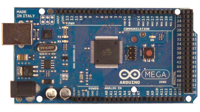
Both are connected to an Arduino Mega 2560 inside my shed, which uses a unified communications protocol to communicate with my Home Control System and send and receive events.

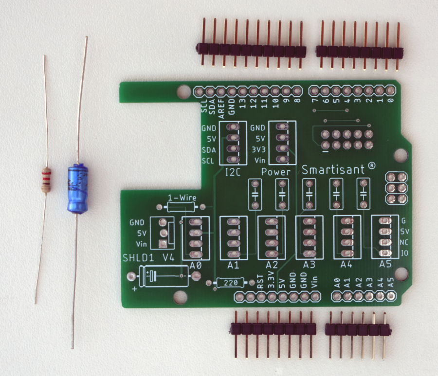
I'm using my Smartisant Arduino Shield SHLD1 to connect the sensors.

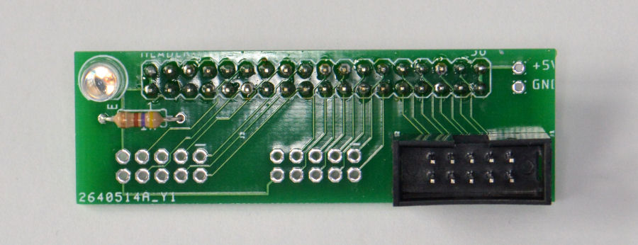
My Smartisant Arduino Header HEAD1 allows up to three 8-channel input or output boards to be easily connected to the Arduino.
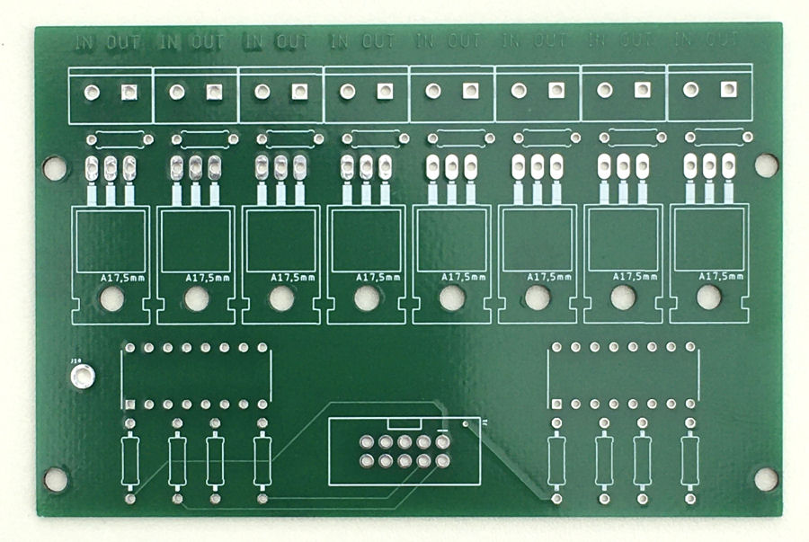
Smartisant Arduino 8-Channel Output Board OP2

For the 12V lighting I'm using my Smartisant 8-Channel Output Board OP2.
Testing

Testing it at night shows it to be plenty bright enough and a nice colour temperature too. This photo was taken before the paving stones were put back. You can see that the far end of the path is not lit up. This will be done using another smart light over the door. This will make it easier to put the key in the shed door lock.
Summary
This is an example of how my smart home building blocks can be used to deliver advanced smart home functionality and encompass the garden within the smart home.
The cost of the hardware to implement the 'Shed Path Light' was around £25 including trunking, LED strip, aluminium profile, ducting and cables.
One thing I'm looking at is whether to combine the Shed Path Light with the Shed Door Light, in terms of control and control electronics. I'm yet to find a scenario where I need to control them independently.
Further Reading
- Smartisant research on smart lighting.


