Motorised Curtains Project • Design
Sections: Overview • Design & Testing • Build • Installation • Summary
The main challenge in automating existing curtains is that they can be fixed in various ways:
- On a standard, straight curtain rail in front of a window.
- On a standard, straight curtain rail inset into a window.
- On a curtain pole.
- On a curve rails that goes into a bay or alcove.
Initially, I'm focussing on curtains (or drapes as they call them in the USA) that run on a standard straight curtain rail. I will be undertaking a project to automate blinds later, as much of the control elements will be common to this project.
Power
A lot of the motorised curtains on the market assume a mains power supply (220V ac in the UK) is used but, I'm mostly interested in a system that uses 24V dc (or even 12V dc) to give me many more options when it comes to installation. This still means that a local mains power supply can be used with a transformer though.
The main reason for taking this approach is that I want all of my motorised curtains to be able to work during power outages.
Curtain Rails/Tracks
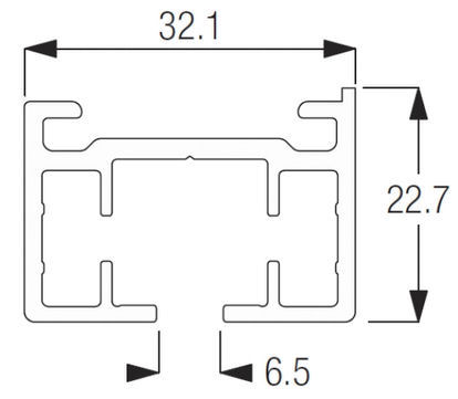
To get high quality and reliable operation, I'm only looking at metal tracks and most seem to be aluminium extrusions. Typically these extrusions have a channel for the rollers/sliders and two more channels for the belt on either side. There is also some means of fixing the track to the ceiling or wall.
From a quality and aesthetics point of view, I want a single piece of track with no joins. Many of the cheaper vendors online will cut the track to make it cheaper to ship and you end up with one or more visible joiners.

A good track has all these features. A 'fixing channel' with protruding lugs to ensure a firm fix to the mounting surface. Two belt channels (one for each direction). A 'support channel', within which the rollers/gliders run. These protrude below the track to provide rings for the curtain to be hung on hangers. The slots between the belt and the support channel are to enable drive to be transferred from the belt to the rollers.
Track Mounting

This is actually the easy bit but, it depends very much on the track being used. Mounts like this Silent Gliss 3004 can be purchased fairly easily at a reasonable price and can be used with 3rd party brackets for wall mounting.
I'm confident that I can fabricate or 3D print some very high quality mounting hardware.
Rollers & Gliders
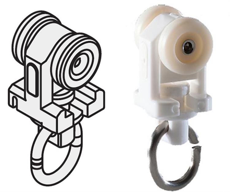
The curtain is fixed to rollers, gliders or runners and these are crucial to getting smooth, quiet operation. All of the best solutions I've seen use rollers with small wheels. I've found many sources of these online but they are not particularly cheap. If I can't find top quality ones at a good price, I will be 3D printing them.
Drive Box
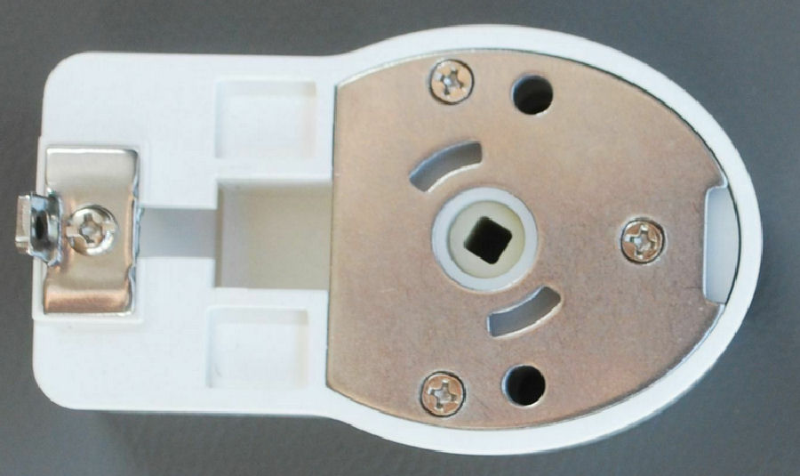
At the end of the track is typically something called a 'drive box' or 'drive unit', which enables a motor to drive the curtain along the track, normally using a toothed belt. This is a Silent Gliss one. The drive box basically mounts the pulley to the track and features a mounting for the motor to connect to the drive pulley.
At the non-driven end the same hardware is often used with a cover plate. I'm looking to build something a bit more subtle and elegant.
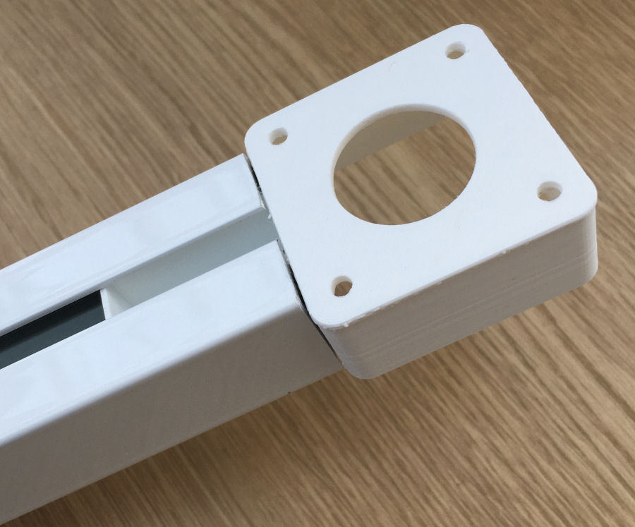
This is my first 3D printed drive box and motor mount.
Pulleys

I found a supplier of HDT5 drive pulleys and bought a pair. The one with the right diameter for my tracks has 16 teeth and a 6mm bore. I was looking to use these metal drive pulleys initially but, now I plan to 3D print these going forward.

To get the exact size pulley required with the right number of teeth, I designed them.
There is a great guide to creating a HTD timing pulley in Fusion 360 available.
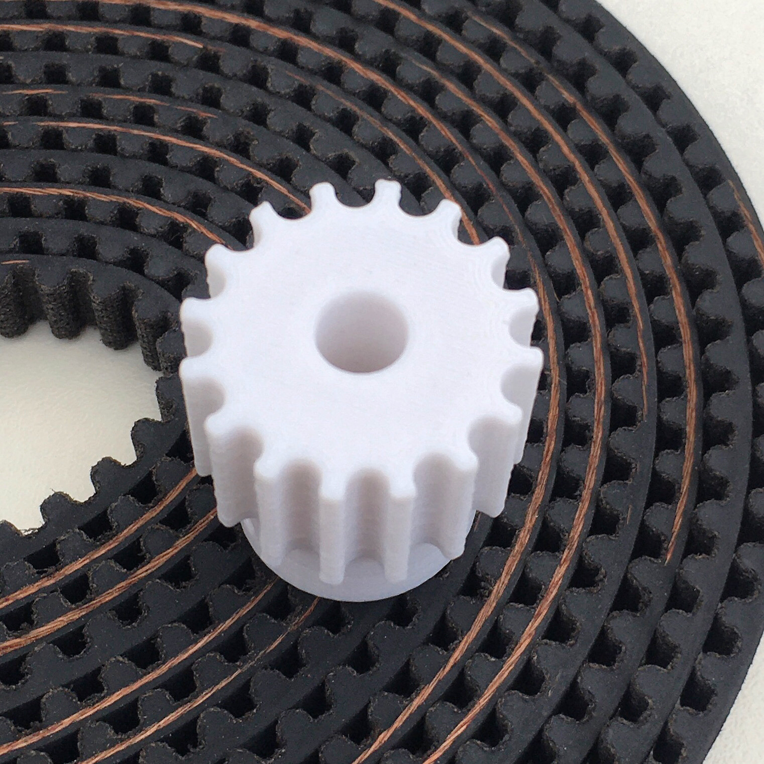
The 3D printed drive pulley.
Drive Belt

Many of the cheaper automated curtains use a cord or wire to provide the drive. Higher quality systems use a toothed belt as it is quieter.
I've used these kind of belts in the past for other projects but, I'm going to be using a top quality HDT5 belt designed for electric scooters and other things. It's extremely strong and efficient and can be bought in long lengths quite cheaply.
Belt Joiner
The HDT5 belt ends will need to be joined together and this will be done with a 3D printed profiled clamp.
Motors & Gearbox
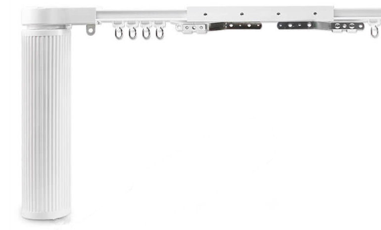
In most of the systems I've seen, a motor fixes to the drive box and is hidden behind the curtain. The commercial units tend to be quite large and unsightly, though they are designed to be hidden behind a curtain. My plan is to build something much more compact.
Knowing the drive pulley diameter and maximum RPM of the motor and gearbox combination, you can work out how fast the curtains will travel. Something between 15cm and 21cm per second seems to be the norm. For my initial testing I using both a geared 12V motor (150rpm with no load) and a high power stepper motor. The stepper motor gives much greater control.
Belt Drive Transfer
This is a device that is fixed to the belt, to enable drive to be transferrred to the rollers/gliders. Typically it clips onto the belt and has an HDT5 profile to hold on tightly. A bar then sticks out through the slot into the suport channel. Ideally, this will not touch the track walls.
I plan to 3D print this part to perfectly fit the HDT 5 9mm belt.
User Interfaces

The primary user interface for manual control of my curtains will be an MK Grid switch (a K4900 on-off-on momentary/retractive switch behind a K3631WHI switch plate). These are high quality switches with a nice feel and are the default choice in my smart home as they are available in a wide range of functions.
These will be labelled using high quality black labels with 'Open' and 'Close', to make the switch function really obvious for guests and to also cover the screws. The switch is only switching low voltage signals to the controller, which will handle the logic and switch 'debouncing'.All of the other user interfaces I use in my home will be able to control these curtains (where permissions allow) including voice control, text control, web apps, etc.
Most of the time, I want my automated curtains to open and close automatically though and my Home Control System can easily be configured to achieve this based on dawn, dusk, sunrise, sunset or via an intelligent, adaptive schedules. Like most of the stuff in my contextual smart home, I'm aiming for a zero touch user experience.
I've chosen this approach because it will also work with 3rd party motors and controllers, though they typically switch mains voltages.
Networking
For this project, my bespoke motor controller will be based around an Arduino and have an RJ45 socket for an Ethernet network connection. This is simply to ensure a very reliable network connection.
I will also be looking at wireless solutions but these are not a priority for now. I'm avoiding proprietary Z-Wave controllers and those using similar technology as they tend to be expensive and involve a realtively 'clunky' user experience. My extensive experience of Z-Wave also proves it doesn't have the level of reliability I require for this project.
Motor Controller
Actually controlling a motor is the easy part. The challenge is in making it stop at the right places, so that it doesn't rip the drive mechanism apart. Typically this is done with sensors or switches to detect the 'end stops'.
As part of my drive for a top quality experience, my controller will use sensors to detect end of travel. It will also have 'soft start' and 'soft stop' capability, to reduce noise and ensure a very smooth operation.
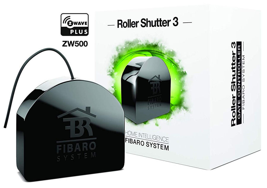
I also plan to test with some readily available controllers and the Fibaro Roller Shutter 3 Z-Wave controller is one of them.
Smart Home Integration
The motor controller, will 'see' switches being pressed and will report these as occupancy events back to my Home Control System, which models all of the switches in my home.
It will also report back curtain state changes to my Home Control System and the controller itself will send a regular heartbeat, so that my HCS knows it is present and working.
The controller will also report an errors, where it thinks things might have jammed for example or the curtains are taking too long to open or close. These will then result in a notification and voice announcement from my Home Control System.
Project Sections
Overview • Design & Testing • Build • Installation • Summary


