3D Printer Monitoring Project
I have already been using my ac voltage detection sensor and ac current sensor on my Ender 3 Pro 3D printer for a while now, to monitor it's activity and allow my smart home to inform me when it has finished its print job.
The challenge is in reliably detecting when the printer has finished the current print job. Current sensing alone is not good enough as the levels involved are very low. Even with the sensitive sensor, this doesn't work reliably. The other option is to detect the beep made by the printer when it finishes but, this is also unlikely to be very reliable.
I want a very reliable and non-intrusive way to work out when my printer had finished its current print job, so I watched it doing its thing and noticed that the X and Y stepper motors move pretty much all the time whilst it is printing. This got me thinking that if I could monitor the rotation of the stepper motor, I could be very confident of when it had finished.
Design & Build
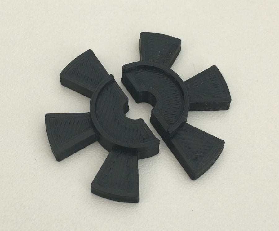
After some careful measuring, I created this 3D 'fan' design in Autodesk Fusion 360, to 3D print. It's in two parts, so that I can be fitted over the 5mm axle on the stepper motor. As it spins, each 'blade' will break the sensor beam and so any movement by the printer will be detected.
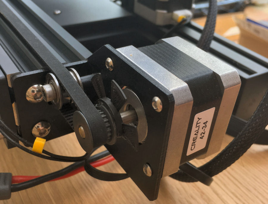
A quick test fit showed that this piece fits nicely and in the right location for the slotted sensor.
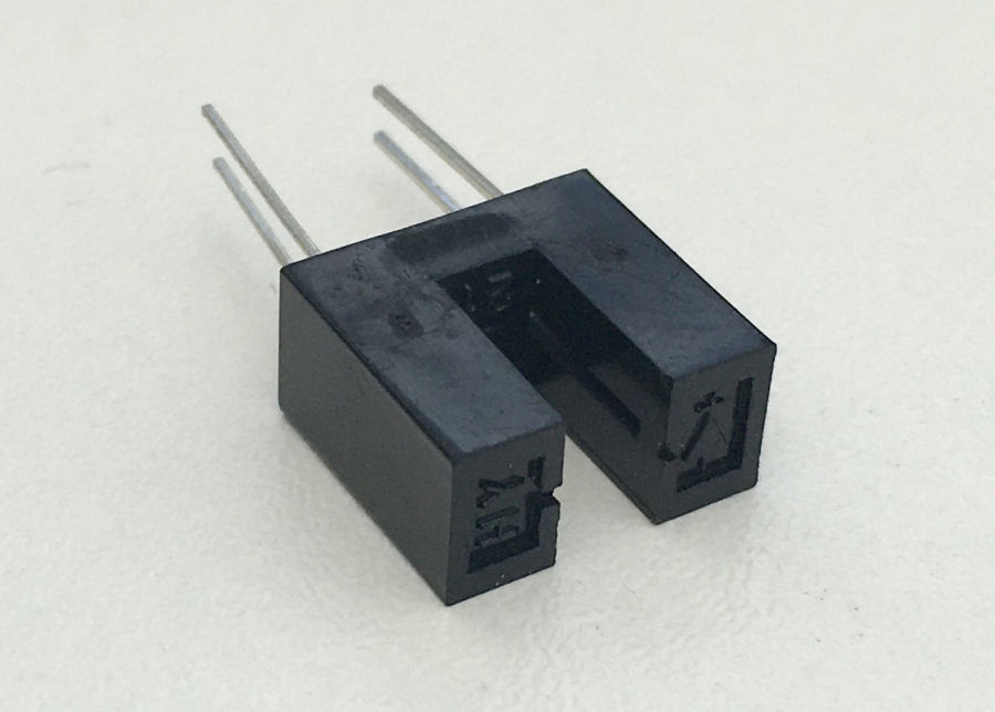
This is the slotted sensor which will detect the 'fan' blades as each one breaks the 'beam' between the 'slots'. The output of this sensor is connected to an Arduino input pin and a 10KΩ pull-down resistor is required.
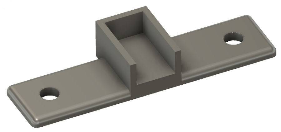
The slotted sensor is fixed to a 3D printed mount and this is them held in place using two outer and existing 3mm motor fixing bolts.
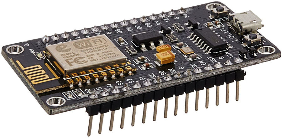
To keep the unit self contained and to make it easy to install, I'm using a Wi-Fi connected Arduino processor. For this project, I've gone with a NodeMCU ESP8266 as I had some spare.
When the power is turned on, the NodeMCU ESP8266 will:
- Wake up and connect to Wi-Fi.
- Measure the printers power usage.
- Send an event to report the printer is on and its power usage.
- Wait for printer activity and detect when the print job has been started.
- Monitor the activity and when none is seen for a few seconds, it will send an event to report that the print job has finished.
When the power is turned off, the NodeMCU ESP8266 should have enough power stored in the dc side of the power supply to do this one thing:
- Send an event to report the printer is off.
Build
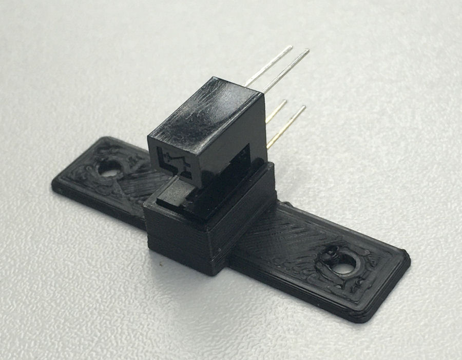
This is the slotted sensor glued to the 3D printed mount. It's designed to offset the sensor perfectly, so that the 'blades' of the 'fan' run through the middle of the slot.
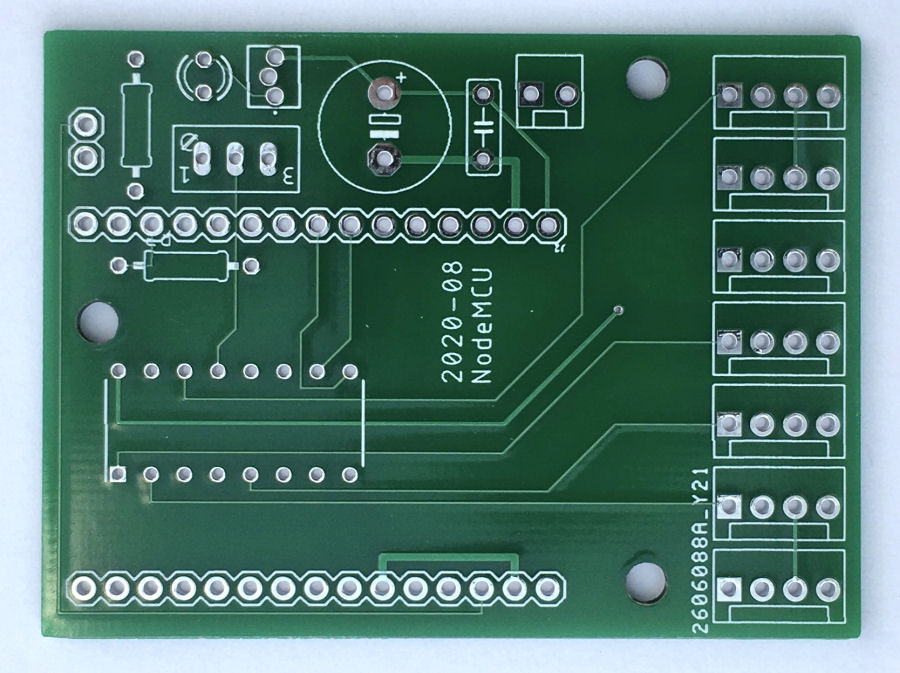
When I did my NodeMCU ESP8266 evaluation, I had 5 PCBs manufactured (minimum order quantity), so I've got a few left over. It just so happens that they are ideally suited to this project and I can use one with some very minor modifications to do what I need here :-)
Voltage Sensing
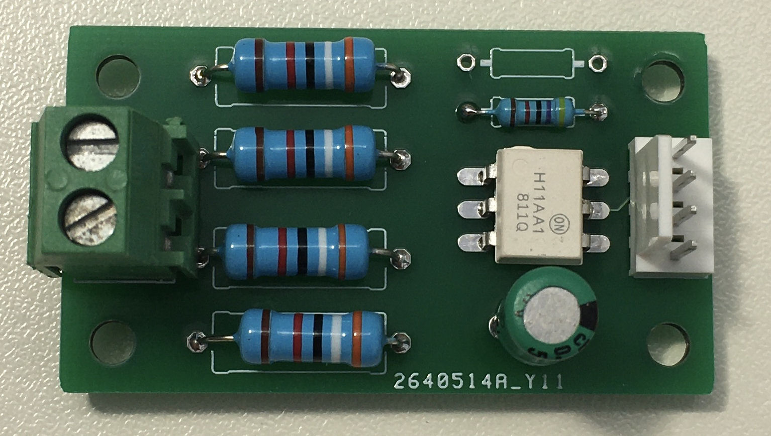
I've designed and built my own ac voltage sensor which is another of my smart home building blocks and has been specifically designed for these types of applications.
It simply connects to any of my Arduino input boards using a 4-way Molex connector. The ac voltage sensor is connected to GPIO13 / D7.
Current Sensing
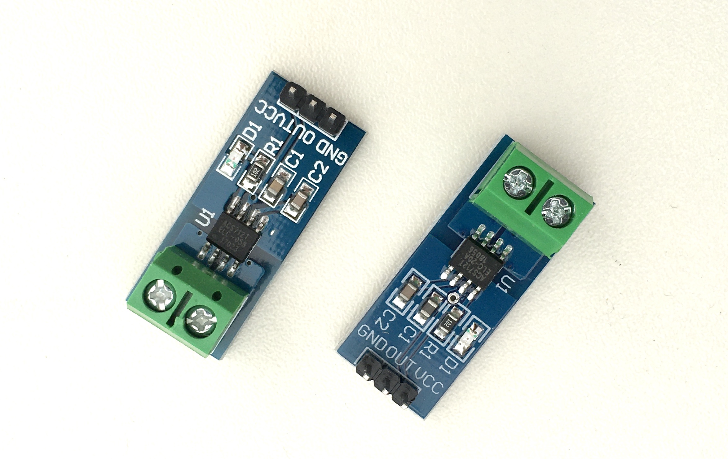
I'm using the ACS712 ac current sensor which needs to be placed in series with the power to the 3D printer in order for the current flow to be sensed. These sensors come in various ratings. I'm using a 5A version here, to get the best possible resolution.
The ACS712 ac current sensor is connected to the A0 pin on the NodeMCU ESP8266 and this is the only analogue input pin available. It accepts an input voltage up to 3.3V.
Power
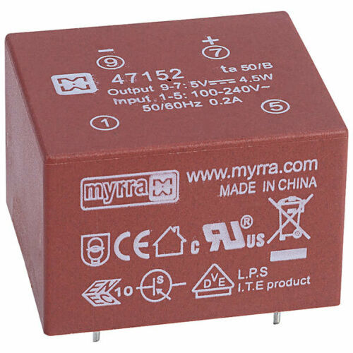
For the power, I'm using a Myrra 47151 3.3V dc power module.
Enclosure
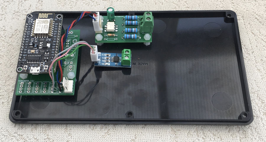
The parts are being mounted inside a black ABS case. All the low voltage stuff is mounted on the base and the mains switch and socket will be mounted on the top.
Software
I'm using a simple state machine to track the various states of the 3D printer:
- ON - Power is detected on boot up.
- HEATING - After some initial activity, there is a delay as the nozzle and bed heat up.
- STARTING - The printing starts an activity is detected.
- PRINTING - Activity has been recently detected.
- FINISHED - Activity stopped.
- OFF - Power switched off.
My code is sending regular updates to my Home Control System as 'Test' events. This allows me to debug and monitor what's going on and to also see how the energy usage varies throughout the print cycle.
Smart Home Integration
Over my many years doing smart home (I started in 2004), I have developed my own library of code for Arduino processors and this includes functions to integrate it into my distributed Home Control System and connect numerous types of sensors. These 'slave processors' can then do clever stuff like local control, self-monitoring of performance, local signal conditioning and rate limiting, send warnings and errors, or host some functions locally.
This maximises reuse across my many smart home projects, making it very quick and easy to develop and test new smart home capabilities. My smart home also employs the concepts of technology abstraction, meaning my smart home is also technology agnostic. This allows old technologies or broken sensors and devices to be swapped out with new ones, with minimal effort and zero reconfiguration.
Most of the Arduino processors installed in my smart home use an Ethernet IP network interface, to enable them to send and receive events with my Home Control System, using my unified communications protocol. Wired networks ensure very low latency and hence a great user experience, though occasionally I will use Wi-Fi.
Adding sensors and devices to my Home Control System is simply a matter of adding one line of JSON for each one, to the main configuration file. This defines the name, zone, object type and also the details of the slave processor it is hosted or controlled by. All the intelligence is within my Home Control System, which receives and sends encrypted events using my unified communications protocol. It sends events to update my smart home on things like the temperature, humidity, fan state, appliance and lighting state changes, occupancy, etc.
By setting a flag for this object (i.e. the 3D printer), I can configure this appliance to automatically update occupancy for the zone in which it resides. This means that the physical switch to turn the printer on and off becomes another occupancy sensor :-)
Testing
With the core elements mounted to the base of the enclosure, I wired them up and started my testing. The current sensor calibration was done using a 275W photographic bulbs and a multimeter.
- Test that the Arduino sends a power usage event every 15 seconds whilst heating.
- Test that the Arduino sends a 'starting' event when printing starts, after the heating cycle.
- Test that the Arduino sends a power usage event every 60 seconds whilst printing.
- Test that the Arduino detects the power being switched off quickly enough to send a power off event before it loses power.
Installation
Aside from the activity sensor, installation is simply a matter of plugging the 3D printer into the socket on this box.
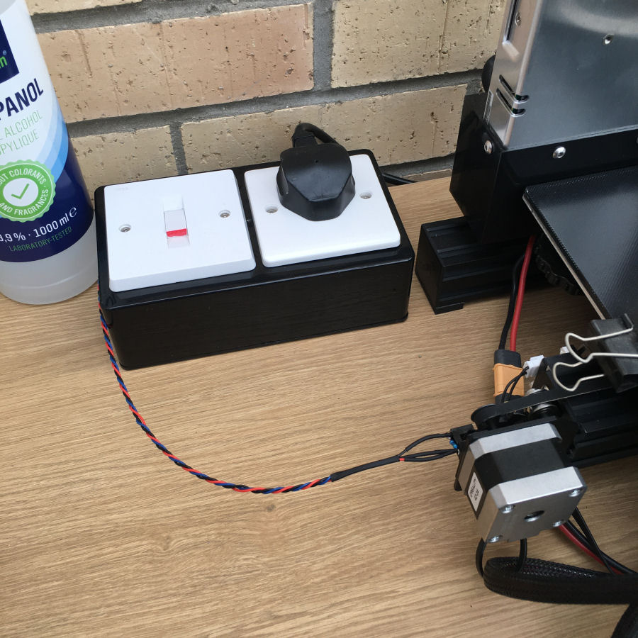
The final installation looks like this, with a nice clear switch to turn the printer on and off.
Examples

A notification is delivered when the print job has completed.
"The Ender 3 Pro print job has finished." - A whole home voice announcement made between certain hours, when a print job has finished.
Summary
This project is working really well and the total cost of all the parts is less than £20.
My contextual smart home 'sees' the 3D printer being switched on immediately and gets an event indicating power usage. The Arduino can detect when the print job has finished and send another event to my Home Control System. It will then send a notification to me and make a whole home voice announcement. When I switch the printer off, the arduino will send another update to my smart home.
This simple concept could be used with a wide range of appliances.
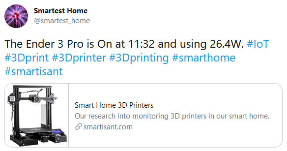
My contextual smart home tweets when my Ender 3 Pro 3D printer is switched on and how much power it is using at start up.
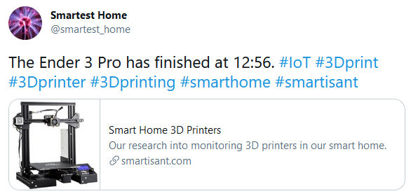
My contextual smart home tweets when my Ender 3 Pro 3D printer has finished its current print job.
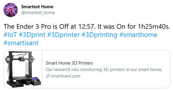
My contextual smart home tweets when my Ender 3 Pro 3D printer is switched off.


