Connected Vehicle Project

This project follows on from my first connected vehicle project, which I used to support my initial research on smart home connected vehicles. It adds some more advanced features and more sensors.
There are four adults in our household currently, with five cars between us. My 'children' are insured to drive at least two of the cars, my wife three of them and myself all of them. This means car tracking cannot be achieved by simply tracking people via their personal devices (e.g. smartphones). There is also more context and insight to be gained by tracking the vehicles in addition to the many techniques I'm currently using to track people.
V2.0 Design
There are a number of new features and capabilities that I'm looking to add in this V2.0 project:
Power
If the processor is going to monitor car battery voltage, then it is going to need a connection to the car's battery but, I don't want to leave the car battery connected as this would result in battery drain through the voltage divider. This means that the cars battery supply is always connected via a relay or the ignition switch.
One of the things I'm looking at it to only use the power via the ignition switch. This would require the ESP8266 to wake up when ignition is applied though.
So when the ignition switch power is applied, we can wake up the processor and enable the relay when required.
DC-DC Convertor
An on-board dc-dc converter is set to output 5.0V dc and this is fed into to the 3.3V Low Drop Out (LDO) regulator. The reason for this is that the 3.3V regulator is also used to power the processor using a rechargeable 18650 3.7V battery.
Battery Charging
When the ignition switch is on, 5V power is applied to the USB battery charging module (via the dc-dc converter). This has a USB type-C connector but also has PCB pins to allow it to be soldered (piggy back fashion) to my own PCB.
When the relay is enabled, the second set of contacts change over the battery +ve from the 3.3V regulator, to the charging circuit. So this means that the 18650 battery is charged when the ignition is on.
Battery Disconnect
If the car is going to be left for a long time, then I can disconnect the unit by unplugging the 3-pin power connector. I can also unplug the 18650 battery. This would be required if the car is being left in an airport car park for example.
Battery Level Monitoring
The 18650 battery will also be connected via a voltage divider. Even with a 100KΩ resistor and 100KΩ potentiometer, this will place a small drain on the battery (approximately 19µA. This is CH0 on the CD4051BE.
The car battery will be connected to a voltage divider and then to one of the analogue inputs but, only when the relay is energised. A voltage divider is used with 100KΩ resistor and 100KΩ potentiometer, to reduce the voltage down to an appropriate level. This is CH1 on the CD4051BE.
Other Updates
This project aims to make the following changes and improvements:
- A switch to allow easy change over between my development and live smart home.
- I will add an LED to indicate Wi-Fi connectivity.
- The processor will go into deep sleep mode and use local battery power when the ignition is off, to allow it to perform various checks and measurements at regular intervals. The assumption is that the battery can last at least 3 months between charges.
- As well as Wi-Fi, I'm going to look at other networking technologies.
- All sensors connected via 4-way Molex connector, to allow eaasy installation and changes.
Networking
Initially, my focus is purely on Wi-Fi connectivity, to keep things simple and to test the key concepts. The next iteration will involved other, more advanced networking and communications. 2.4GHz Wi-Fi is fine for now though. It has good range and my cars connect to my home before it has come to a stop up onto my drive.
Processor Wake-Up
To use timer wake up with ESP8266, you need to connect the RST pin to GPIO 16 which is labelled as D0, in a NodeMCU board. If you take a look at the NodeMCU pinout, you can see that GPIO 16 is a special pin and it has a WAKE feature.
The RST pin of the ESP8266 is HIGH while the ESP8266 is running. When the RST pin receives a LOW signal, it restarts the microcontroller. If you set a deep sleep timer with the ESP8266, once the timer ends, GPIO 16 goes LOW pulling the RST pin LOW, to wake up the ESP8266 after a set period of time.
My plan is to use both GPIO 16 and an opto-coupler (connected to the ignition), to pull the RST pin LOW, so that both will restart the ESP8266.
Indicators
An blue LED is used to indicate when the processor has connected to Wi-Fi.
Sensors
Ignition
One of the inputs to the processor is a sensor that detects the ignition being switched on and off. Because this is a 12V signal, it is interfaced via an optocoupler, to translate this to a 3.3V signal. The digital input pin is pulled up to 3.3V using a 39KΩ pull-up resistor. The opto-coupler pulls the D4 pin to ground when the ignition is on.
Analogue Sensors
There is only one analogue input pin and the ADC has a 10-bit resolution, which means you will get values between 0 and 1023. The ESP8266 ADC pin input voltage range is 0 to 1V if you are using the bare chip. The NodeMCU ESP8266 board comes with an internal voltage divider, so the input range is 0 to 3.3VCH0 18650 Battery Voltage
This is done using a voltage divider.
CH1 Car Battery Voltage
This is done using a voltage divider.
CH2 Cockpit Temperature
The cockpit temperature is measured using a thermistor. Power for this sensor is provided by the D1 output pin, to enable sensors to effectively be switched off.
CH3 Cockpit Humidity
The cockpit humidity is measured using a HIH-4000 series humidity sensor. The main issue with this sensor is that it requires a 5V dc power supply and will not work from a 3.3V supply. This sensor is powered by the dc-dc convertor and is therefore only available when the ignition is enabled.
The 5V supply means that it requires a voltage divider, albeit a very small one, using a 10KΩ resistor and 100KΩ potentiometer.
I looked at using a DHT22 for temperature and humidity but this also requires a high supply voltage than 3.3V.
Implementation
Power
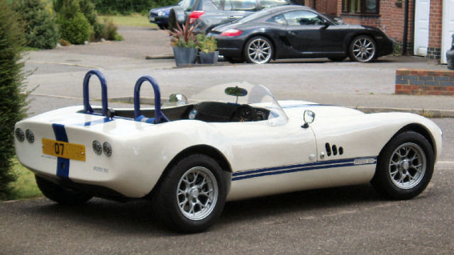
Getting access to permanent power and a switched ignition feed is fairly easy but, it depends very much on the car. In a car like my Fisher Fury R1 kit car this is easy as I built the wiring loom for the car from scratch. For the Eunos Roadster it is also quite easy as feeds for things like the cigarette lighter are switched via the ignition and this is true of most modern cars. Sometimes, I need to run an additional wire for the permanent power feed and this is always done using a 3A in-line blade fuse holder.
PCB V2.0
T.B.C.
Software
The processor is always looking for my home Wi-Fi network and will connect to it when it is in range. It keeps track of how long it has been running, so it knows if it is already home or has arrived home at the end of a longer journey. The code is basically a state machine that uses the following states: BOOTUP, STARTUP, CONNECTED, DISCONNECTED, RECONNECTED, SHUTTINGDOWN, SHUTDOWN.
Smart Home Integration
Over my many years doing smart home (I started in 2004), I have developed my own library of code for Arduino processors and this includes functions to integrate it into my distributed Home Control System and connect numerous types of sensors. These 'slave processors' can then do clever stuff like local control, self-monitoring of performance, local signal conditioning and rate limiting, send warnings and errors, or host some functions locally.
This maximises reuse across my many smart home projects, making it very quick and easy to develop and test new smart home capabilities. My smart home also employs the concepts of technology abstraction, meaning my smart home is also technology agnostic. This allows old technologies or broken sensors and devices to be swapped out with new ones, with minimal effort and zero reconfiguration.
Most of the Arduino processors installed in my smart home use an Ethernet IP network interface, to enable them to send and receive events with my Home Control System, using my unified communications protocol. Wired networks ensure very low latency and hence a great user experience, though occasionally I will use Wi-Fi.
Adding sensors and devices to my Home Control System is simply a matter of adding one line of JSON for each one, to the main configuration file. This defines the name, zone, object type and also the details of the slave processor it is hosted or controlled by. All the intelligence is within my Home Control System, which receives and sends encrypted events using my unified communications protocol. It sends events to update my smart home on things like the temperature, humidity, fan state, appliance and lighting state changes, occupancy, etc.
Each vehicle is part of my contextual smart home's models and each one is essentially a mobile zone. This means all of the sensors and things like occupancy are inherited from my smart home, including all of its common capabilities.
Each Arduino installed in or on a vehicle, connects to our home Wi-Fi network when in range and once connected, can send events using my smart home's unified communications protocol.
Summary
Having the smart home track vehicles means that it has a lot more useful context and can do some very clever things, to improve the smart home user experience. When cars are linked to one individual (e.g. my kitcar is only driven by me), the the smart home can provide a personalised user experience.

My @smartest_home sometimes tweets when a vehicle has been started.
At night, this will extend the time the drive light stays on and will keep extended this time, whilst the car is still on the drive.

When my contextual smart home spots cars arriving home or knows they are still on the drive, it can do useful things like turning drive and porch lights on and keeping them on whilst the drive is occupied. It could also open automated garage doors, knowing which cars go into which garage.
It is also possible to link cars arriving home to the front door lock and unlock it automatically.
Because this is part of the wider context of my contextual smart home, it can also let me know when people or cars arrive home, using a notification or voice announcement if I'm already at home. This is addition to the context from personal devices like smartphones.
This is only my first project in this space, to understand what's possible and useful. I'm looking at other networking technologies with longer range and even greater legacy integration with my vehicles.


