CAN Bus Interface Project

As part of my Open-Source Sports EV (OSSEV) project, I'm investigating CAN bus technologies.
Research
ODB-2 Port
The CAN bus on most cars is exposed via an ODB-2 J1962 connector under the dash. This is a 16-pin D-shape connector with 2 rows of 8 pins. How the pins are used varies across different brands of cars but, a lot of the pins are common. In most Mazda cars, the pins are:
- N/C
- J1850 Bus+
- LS CAN Hi = Low speed (125Kb) CAN bus. This bus used for some IC, RFA and other units.
- CGND = Chassis ground.
- SGND = Signal ground.
- CAN High = J-2284
- K-LINE = Diagnostic, (ISO 9141-2 and ISO/DIS 14230-4)
- N/C
- N/C
- J1850 Bus-
- LS CAN Low = Low speed (125Kb) CAN bus. This bus used for some IC, RFA and other units.
- N/C
- N/C
- CAN Low = J-2284
- ISO 9141-2 L-LINE = Diagnostic, (ISO 9141-2 and ISO/DIS 14230-4)
- +12V = Battery power.
Transceiver Module

For this project, I'm using these Arduino compatible 16MHz CAN bus MCP2515 transceiver modules. These are small at just 40mm × 25mm. It supports CAN protocol version 2.0B and can be used for communication at speeds up to 1Mbps. It uses the MCP2515 CAN controller IC and the TJA1050 CAN transceiver IC. The MCP2515 IC is a standalone CAN controller with an integrated SPI Interface for communication with microcontrollers like an Arduino. The TJA1050 IC provides the interface between the MCP2515 and the physical CAN bus.
Mazda CX-30

Most of my initial testing is going to be done using our Mazda CX-30, which has a readily accessible ODB-2 diagnostics port just inside the driver's door. I've labelled the pins in this photo.

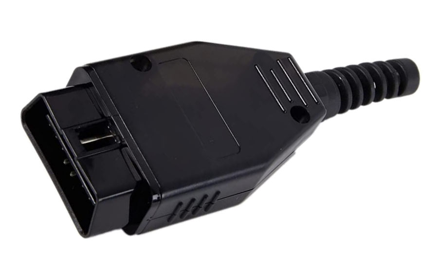
To connect to the CX-30's ODB-2 port (type A), I bought a OBD-2 J1962 16-pins male connector plug on Amazon.
The J1962 specification provides for two standard hardware interfaces, type A and type B. Both are female, 16-pin (2x8), D-shaped connectors, and both have a groove between the two rows of pins. Type B has the groove interrupted in the middle, so you can't plug a type A male connector into a type B socket. You can, however, plug a type B male plug in a type A female socket. The type A connector is used for vehicles that use 12V supply voltage, whereas type B is used for 24V vehicles (where it is a requirement to mark the front of the D-shaped area in blue).
CAN Bus Overview
CAN bus uses two wires for communication, called CAN high and CAN low. A CAN controller is connected to all the components on the network via these two wires and each network node has a unique identifier. All the CPUs/ECUs on the bus are connected in parallel and all the nodes see all of the data, all of the time. A node only responds when it detects its own identifier. Individual nodes can be removed from the network without affecting the other nodes.
When the CAN bus is in idle mode, both lines carry 2.5V. When data bits are being transmitted, the CAN high line goes to 3.75V, and the CAN low drops to 1.25V, thereby generating a 2.5V differential between the lines. Power can be supplied through the CAN bus or separately. It can be integrated into the same cable as the CAN bus lines by using a 4-wire cable.
Wiring Colours
CAN is generally wired with yellow as CAN-High and green as CAN-Low, so I'm sticking with this conventions. I'm using red for 12V and black for GND.
MCP2515 CAN Bus Library
There a CAN Bus libraries available for the Arduino IDE. These implements CAN V2.0B at up to 1Mb/s and an SPI Interface up to 10 MHz. IT supports standard (11 bit) and extended (29 bit) data and remote frames, with two receive buffers with prioritized message storage. The libraries make it remarkable easy to send and receive data over a CAN Bus quickly.
Mazda CAN Bus Protocol
The Mazda CAN Bus protocol has mostly been reverse engineered and published on-line. Most Mazda cars have two CAN buses: a high speed one (500KHz) on which most of the essential systems (ECU, ABS, etc.) were connected and a lower speed (125KHz) network on which accessories such as the audio system were connected. These two networks both enter the instrument panel which acts as the gateway to allow some messages to pass between them.
Testing

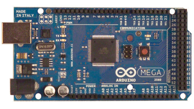
For my initial testing, I'm using the Arduino Mega 2560. It has loads of processing power, memory and lots of IO capability. There is also a very cheap IP network interface for it.
This requires a pinoutguide.com - Mazda OBD II diagnostic interface pinout


