Bluetooth Low Energy (BLE) Smart Home Project
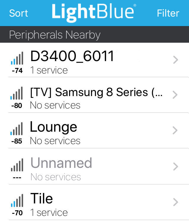
I was experimenting with the LightBlue iOS app and noticed that it revealed a large number of Bluetooth Low Energy (BLE) enabled devices in my contextual smart home. This includes things like our Samsung SUHD TV, Apple TVs, Nikon D3400 DLSR camera and also our many Tile Pro trackers.
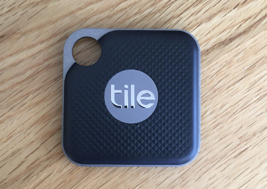
I like my Tile Pro trackers because that have replaceable batteries (CR2032 3V coin battery) and battery life is very good.
This got me thinking that if I could add a BLE scanner to my contextual smart home, then this would be yet another good source of occupancy and presence.
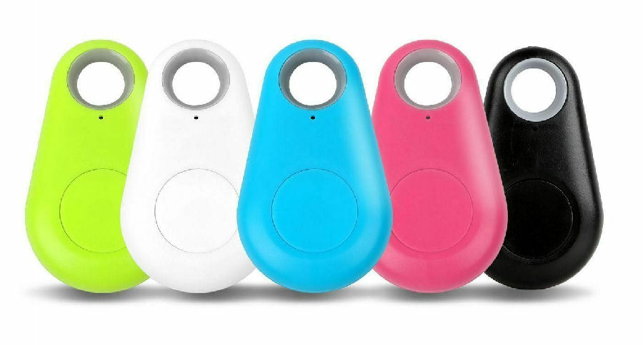
I'm also planning to test with these cheaper iTag BLE 4.0 devices.
Design
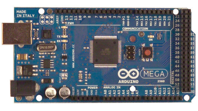
My planned approach for this project is to use an Arduino Mega 2560 which will be connected to my home IP network using an Ethernet shield. I really like these processors as they are incredibly reliable, secure and I've developed a library of code over the years to allow simple connection to my smart home.
The Arduino processor will scan for BLE devices and report those seen to my Home Control System by sending it 'spotted' event at regular intervals. These events also contain a zone, so my smart home can already do tracking of people down to zone level.My Home Control System uses JSON files to configure it. This includes simple configuration of the models for every known device within it and its associated network interfaces (Ethernet, Wi-Fi and Bluetooth). This means my smart home can track the coming and going of every networked device in our home. The models also support ownership, where this makes sense. This allows my contextual smart home to track individual people and then use this to deliver a personalised user experience.
HC-05
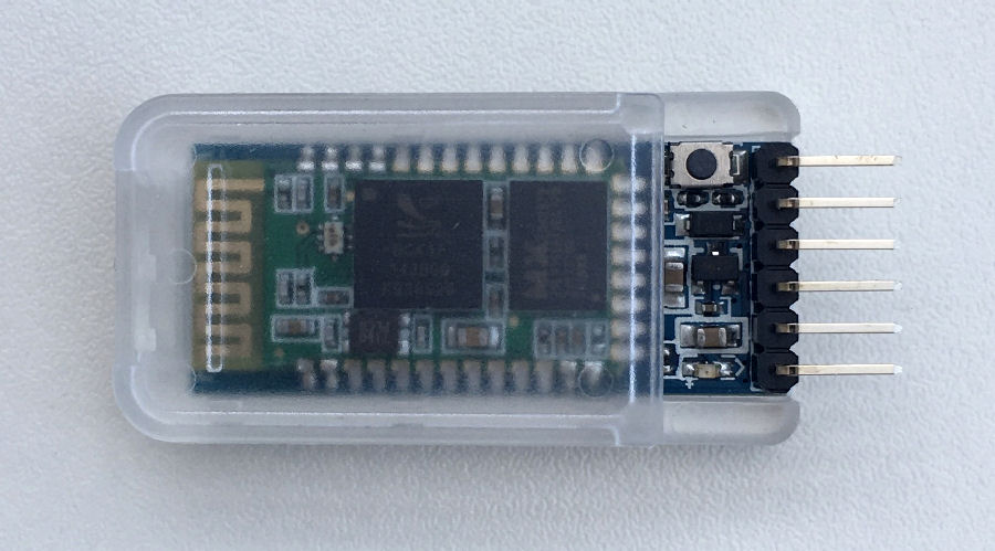
I bought a DSD TECH HC-05 Bluetooth serial pass-through module on Amazon for about £7.
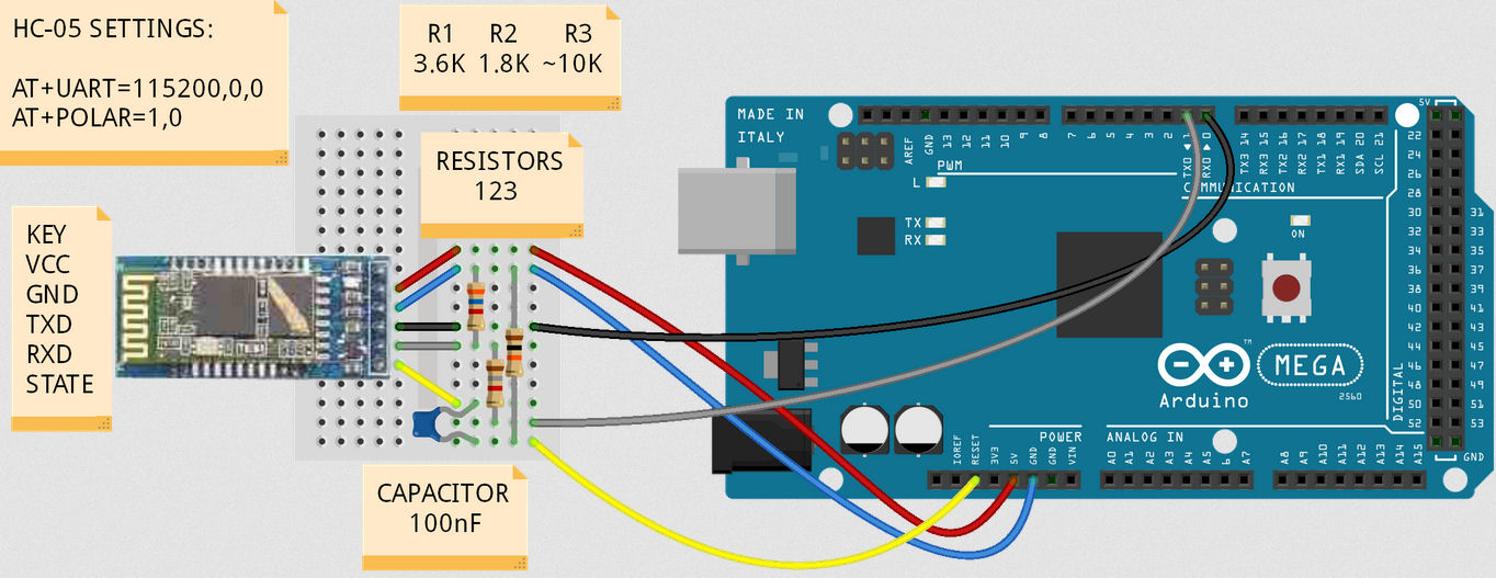
The HC-05 can be easily interfaced to any Arduino but I'm using a Mega 2560. The Mega 2560 uses 5V logic levels, whilst the HC-05 uses 3V. To enable a safe and reliable connection, a voltage divider is used to translate the 5V signal from the Arduino into a 3V signal. The 3V signal from the HC-05 is high enough to be used reliably with an Arduino digital input pin.
This image showing the electrical connections is from this Arduino forum thread.
HM-10
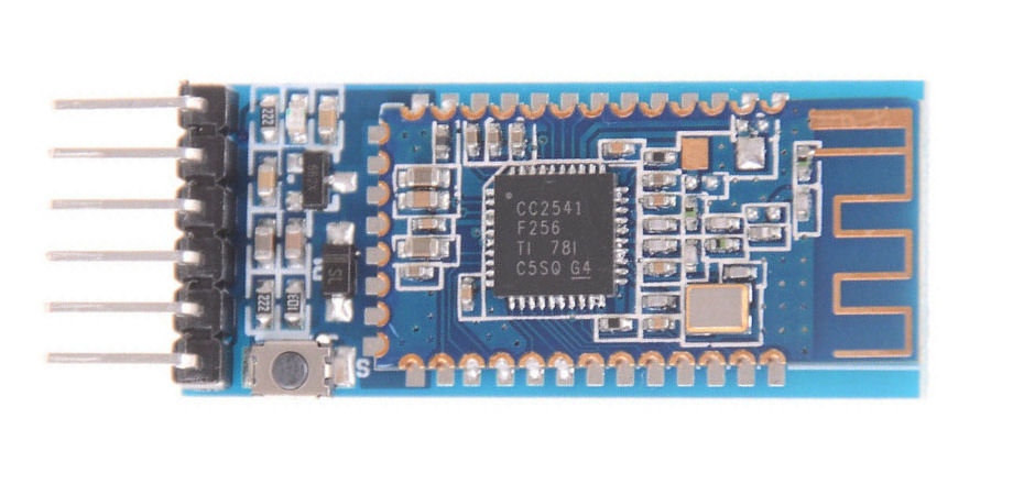
The HM-10
My device has the CC2541 chip and 32MHz crystal.
ESP32
Don't want to use this as it connects via Wi-Fi. https://www.dfrobot.com/product-1590.html?tracking=5972173208374HM-10 Connections
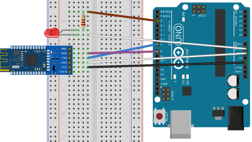
The connections are fairly simple and the HM-10 has labels for the pins on the underside. VCC (orange) goes to +5V. GND (black) goes to Arduino ground. TX (green) goes to Arduino RX. RX (blue) needs a voltage divider from Arduino TX.
The voltage divider is to 'voltage drop' the signal from the Arduino from 5V levels to 3.3V. This is achieved using a 1K8Ω and a 3K8Ω resistor.
Bluetooth Software
Testing
iTag
Out of the box, the iTag doesn't do anything until you switch it on (press and hold button for 2 seconds, it beeps twice). It then appears as a device called 'iTag' and the blue LED flashes every 3 seconds. I'm not sure how long the battery would last when used like this but after about a minute the blue LED stops flashing, to improve battery life.
You can actually switch the iTag off by pressing and holding the button for 5 seconds.
The range of the iTag is not as good as the Tile device. At a few centimeters, the iTag signal is -35 and the Tile -20. At 3 meters, the iTag is -59 and the Tile is -56. At 6m, the iTag is -70 and the Tile -62.
Summary
This project adds another layer of information into my smart home's occupancy and presence capability. There is no one technology that can do this well on its own, so a layered approach works best, giving the most accurate and timely results. This is further support of our hybrid technology approach to smart home.


