Sequenced Stair Lighting Project

Sequenced stair lighting is something that comes up a lot in the various home automation forums, so I thought I'd take a look at how this might be done in a new build and also as a retro-fit solution in an existing home.
In my current home I have 12 steps. My initial design and testing is based on a design that has up to 16 steps but the exact number is configurable and could go up 32 if reqlly required.
Requirements
My thinking on the requirements is that I want the following features:
- The whole system is powered by a 12V dc power source, so that the power can be protected by my UPS if required.
- Two beam break sensors at the top and bottom of the stairs can be used to trigger the sequential lighting effects. These are also both occupancy sensors that contribute to the wider whole home context of my contextual smart home.
- As well as working in sequential mode, I also want some permanent low-level safety lighting to be an option at each step. This would use warm-white LEDs.
- I would also like to be able to switch on some emergency lighting on each step. This would use red LEDs.
- I want to be able to enable/disable the sequential lighting via my contextual smart home and also be able to do adaptive scheduling using a controller.
- My solution must support up to 16 steps.
- The latency must be really low, to provide the best possible user experience.
- It would be nice if this lighting also supported effects.
Design
Beam Break Sensors
My design uses beam break sensors because these provide the most accurate and timely detection, with very low latency. They are also the best sensors in terms of lack of false triggering.
Some people have used PIR sensors (motion sensors) but, these will give a much poorer user experience and have a much wider field of view.
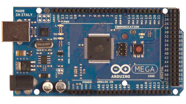
Arduino Mega 2560

The main reason for using the Arduino Mega 2560 is that it has loads of IO capability and enough memory to do powerful control and integration with my contextual smart home.
I'm using an Ethernet shield with this processor to provide a wired Ethernet connection and to enable full integration with my contextual smart home.
Smartisant Arduino Shield

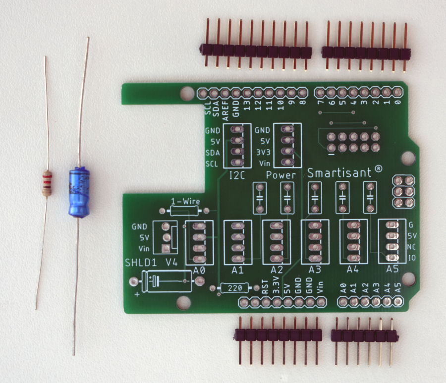
I'm using my Smartisant Arduino Shield SHLD1 to connect the sensors.
Smartisant Arduino Header

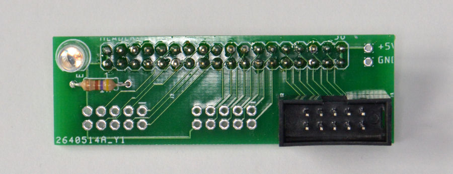
My Smartisant Arduino Header HEAD1 allows up to three 8-channel output boards to be easily connected to the Arduino.
Smartisant Arduino 8-Channel Output Board OP2

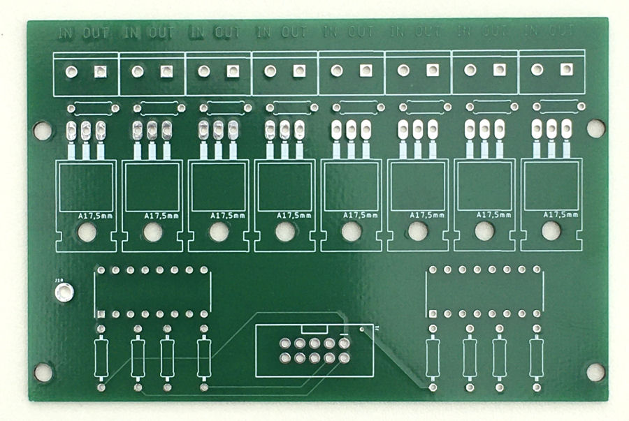
For the 12V lighting I'm using my Smartisant 8-Channel Output Board OP2. Two are required to control 16 lights and this board is PWM capable, so I can use this later if required.
Lights

The only way to get the features I want is going to be by 3D printing suitable light fixtures to mount into the wood running up my stairs. I want something subtle and small so I'm using 40mm diameter acrylic 'opal' discs as a cover to provide diffuse lighting. When mounted on a white painted surface, they are almost invisible. They give a simple but quality feel. They could even be inset and flush to the surface, if your woodworking skills are up to the job.

The acrylic disc sits in front of this 3D printed LED housing and acts as a diffuser. I'm still trying out various designs though. All the LEDs used are clear, so they are invisible when off. The outer ring of 6 are warm white and the main lighting.
The main lighting, emergency lighting and safety lighting elements are all powered from a 12V dc supply and hence all capable of being dimmed using PWM. This results in 4 wires (including the ground) to each light module. Current limiting resistors are installed within each module to limit the current and allow the LEDs to work with a 12V supply.

The safety lighting LEDs are warm white, diffuse LEDs and driven at 4mA using a LM317 regulator. This ensure they all look even brightness at night and they provide just the right level of light to see by, without effecting your night vision.
Build
Models
My smart home already models the 'Safety Lighting' and 'Emergency Lighting'.
For this project I've also modelled the following objects:
- 'Stair Lights' - Binary (on/off) lighting that can be controlled by my smart home and are enabled or disabled this way.
- 'Top Stair Beam' - Has a object type of 'Beam' and is either 'Open' or 'Closed'.
- 'Bottom Stair Beam' - Has a object type of 'Beam' and is either 'Open' or 'Closed'.
Arduino Software
Over the years, I've developed a library of code that enables projects like this to be easily and fully integrated into my contextual smart home.
The Arduino software uses interrupts to detect the beam break sensors being triggered. This means connecting them to pins 2 and 3.
If the top one is triggered, then the lights will light in sequence from top to bottom. If the bottom one is triggered, then the sequence will be reversed. I've also written my code so that it works independently in both direction, so if both were triggered at the same time the sequence would start at both ends and in both directions. It will also work if the beams were triggered at slightly different times.
The software will be made available here very soon.
Defines
In the Arduino code are some defined configurable parameters:
- START_PIN 22 - This equates to the bottom of the stairs.
- END_PIN 37 - This equates to the top of the stairs.
- STEP 200 - This is the time in ms between each LED activating in sequence.
- DURATION 2000 - This is the time in ms each LED stays lit.
Effects
Like a lot of my own built lighting, this project also supports effects. These can be requested via any of the user interfaces to my contextual smart home. The effects currently supported are:
- Nightrider
- Strobe
- Twinkle
Testing

To do the initial testing, I'm using a couple of my Smartisant Output Tester OPTEST1 boards. These make it really easy to test that things are working before I connect the actual lighting, including the sensor activation and effects.
Instead of beam break sensors, I'm using micro-switches for my initial testing and these are easily swapped out later as they connect using a 4-way Molex connector to the Smartisant Arduino Shield SHLD1.
This is some basic testing of the light sequencing to show what it would look like. The step between each LED and the duration each one is on for can be easily configured.
Smart Home Integration
Over my many years doing smart home (I started in 2004), I have developed my own library of code for Arduino processors and this includes functions to integrate it into my distributed Home Control System and connect numerous types of sensors. These 'slave processors' can then do clever stuff like local control, self-monitoring of performance, local signal conditioning and rate limiting, send warnings and errors, or host some functions locally.
This maximises reuse across my many smart home projects, making it very quick and easy to develop and test new smart home capabilities. My smart home also employs the concepts of technology abstraction, meaning my smart home is also technology agnostic. This allows old technologies or broken sensors and devices to be swapped out with new ones, with minimal effort and zero reconfiguration.
Most of the Arduino processors installed in my smart home use an Ethernet IP network interface, to enable them to send and receive events with my Home Control System, using my unified communications protocol. Wired networks ensure very low latency and hence a great user experience, though occasionally I will use Wi-Fi.
Adding sensors and devices to my Home Control System is simply a matter of adding one line of JSON for each one, to the main configuration file. This defines the name, zone, object type and also the details of the slave processor it is hosted or controlled by. All the intelligence is within my Home Control System, which receives and sends encrypted events using my unified communications protocol. It sends events to update my smart home on things like the temperature, humidity, fan state, appliance and lighting state changes, occupancy, etc.
Summary
This is another great example of how my smart home building blocks can be used to deliver advanced smart home functionality. It doesn't have to be integrated to a smart home though and could work as a stand-alone solution, with just power.
This project would be a lot simpler if it didn't involve individually controllable lights for each step, with all the lights just coming on together. This would be a much cheaper solution too.
Although this project is designed for up to 16 steps, it could easily be extended to 32 if required.
There are other ways to run lighting along the lenght of a flight of steps. LED strip lighting is one option and individually address LED strips would enable a lot of the functionality I've described here.
The Arduino Mega 2560 described here has loads of spare capacity and could have a number of other sensors connected to it as well.
Further Reading
- My related project project on emergency lighting.
- My related project project on safety lighting.
- Smartisant research on emergency lighting.
- Smartisant research on safety lighting.


